1-4-5.INSUL-8 8字型電軌(INSUL-8 CONDUCTOR)
 點擊圖片放大
1-4-5.INSUL-8 8字型電軌(INSUL-8 CONDUCTOR)
1.C&W電軌系統(SAF-T-BAR)新目錄
1-1.SAF-T-BAR C型電軌(C SERIES CONDUCTOR) 下載down load
1-2.SAF-T-BAR H型電軌(H SERIES CONDUCTOR) 下載down load
1-3.SAF-T-BAR T型電軌(T SERIES CONDUCTOR) 下載down load
1-4.INSUL-8 8字型電軌(INSUL-8 CONDUCTOR) 下載down load
1-5.INSUL-8側向8型電軌(INSUL-8 SIDE CONTACT CONDUCTOR BAR) 下載down load
1-6.CLUSTER電軌CLUSTER BAR 下載down load
| ||||||||||||||||||||||||||||||||||||||||||
| |||||||||||||||||||||||||||||||||||||||||||||||||
| ||||||||||||||||||||||||||||||||||||||||||||||||||||||||
Item | Rigid PVC Cover | Medium Heat Cover | High Heat Cover | |||
Part No. | Wt lb (kg) | Part No. | Wt lb (kg) | Part No. | Wt lb (kg) | |
Conductor Bar, 20 ft (6.10 m) 11016 | 23.6 (10.71) | 11035 | 22.1 (10.02) | 11054 | 24.6 (11.16) | |
Conductor Bar, 10 ft (3.05 m) 11017 | 11.8 (5.35) | 11036 | 11.0 (4.99) | 11055 | 12.3 (5.58) | |
Expansion Section, 10 ft (3.05 m) | 11063 | 18.5 (3.39) | 11069 | 17.3 (7.85) | 11075 | 20.0 (9.07) |
Power Feed | 11094 | 2.6 (1.18) | 11094 | 2.6 (1.18) | 11094 | 2.6 (1.18) |
End Cover 12171 0.2 (0.09) 11633 0.2 (0.09) 11633 0.4 (0.18)
更多商品
1-4-4.INSUL-8 8字型電軌(INSUL-8 CONDUCTOR)
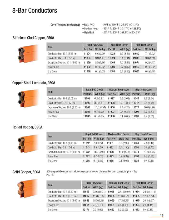
1.C&W電軌系統(SAF-T-BAR)新目錄 1-1.SAF-T-BAR C型電軌(C SERIES CONDUCTOR) 下載down load 1-2.SAF-T-BAR H型電軌(H SERIES CONDUCTOR) 下載down load 1-3.SAF-T-BAR T型電軌(T SERIES CONDUCTOR) 下載down load 1-4.INSUL-8 8字型電軌(INSUL-8 CONDUCTOR) 下載down load 1-5.INSUL-8側向8型電軌(INSUL-8 SIDE CONTACT CONDUCTOR BAR) 下載down load 1-6.CLUSTER電軌CLUSTER BAR 下載down load 8-Bar conductor bars come with cover and connector pins installed. Bars are available in 40A, 90A, 110A, 250A, 350A, 500A capacities (@ 600 volts maximum). Expansion Sections are listed below. These are required to compensation for thermal expansion; every 350 feet (106.7 m) for 40A, 90A, and 100A systems or 250 feet (76.2 m) for 250A, 350A, and 500A systems. Power Feeds bring outside power to the conductor bar. Factory installed covers are available in: Rigid PVC: -10O F to 160O F (- 23.30C to 71.10C) Medium Heat: - 25O F To 250O F (- 31.70C to 121.10C) High Heat: - 60O F To 400O F (-51.10C to 204.20C) Item Rigid PVC Cover Med Heat Cover High Heat Cover Part No. Wt lb (kg) Part No. Wt lb (kg) Part No. Wt lb (kg) Conductor Bar, 10 ft (3.05 m) 14299 7.0 (3.18) 24304 6.6 (2.29) 24307 7.5 (3.40) Conductor Bar, 5 ft (1.52 m) 14823 3.5 (1.59) 24305 3.3 (1.50) 24308 3.8 (1.72) Expansion Section, 10 ft (3.05 m) 24279 7.5 (3.40) 24306 7.0 (3.18) 24309 8.2 (3.72) Power Feed 11091 0.4 (0.18) 11091 0.4 (0.18) 11122 0.4 (0.18) End Cover 11088 0.1 (0.05) 11088 0.1 (0.05) 11633 0.1 (0.05) Item Rigid PVC Cover Med Heat Cover High Heat Cover Part No. Wt lb (kg) Part No. Wt lb (kg) Part No. Wt lb (kg) Conductor Bar, 10 ft (3.05 m) 22135 4.4 (2.00) 22141 4.1 (1.86) 22147 4.9 (2.22) Conductor Bar, 5 ft (1.52 m) 22136 2.2 (1.00) 22142 2.1 (0.95) 22148 2.5 (1.14) Expansion Section, 10 ft (3.05 m) 22140 6.7 (3.31) 22146 6.3 (2.86) 22152 7.4 (3.36) Power Feed 11091 0.4 (0.18) 11091 0.4 (0.18) 11122 0.4 (0.18) End Cover 22070 0.1 (0.05) 22070 0.1 (0.05) 11633 0.1 (0.05) Item Rigid PVC Cover Med Heat Cover High Heat Cover Part No. Wt lb (kg) Part No. Wt lb (kg) Part No. Wt lb (kg) Conductor Bar, 10 ft (3.05 m) 11000 4.4 (2.00) 11019 4.1 (1.86) 11038 4.9 (2.22) Conductor Bar, 5 ft (1.52 m) 11001 2.2 (1.00) 11020 2.1 (0.95) 11039 2.5 (1.13) Expansion Section, 10 ft (3.05 m) 11057 6.7 (3.31) 11064 6.3 (2.86) 11070 7.4 (3.36) Power Feed 11091 0.4 (0.18) 11091 0.4 (0.18) 11122 0.4 (0.18) End Cover 11088 0.1 (0.05) 11088 0.1 (0.05) 11633 0.1 (0.05)
1-4-3.INSUL-8 8字型電軌(INSUL-8 CONDUCTOR)
1.C&W電軌系統(SAF-T-BAR)新目錄 1-1.SAF-T-BAR C型電軌(C SERIES CONDUCTOR) 下載down load 1-2.SAF-T-BAR H型電軌(H SERIES CONDUCTOR) 下載down load 1-3.SAF-T-BAR T型電軌(T SERIES CONDUCTOR) 下載down load 1-4.INSUL-8 8字型電軌(INSUL-8 CONDUCTOR) 下載down load 1-5.INSUL-8側向8型電軌(INSUL-8 SIDE CONTACT CONDUCTOR BAR) 下載down load 1-6.CLUSTER電軌CLUSTER BAR 下載down load Conductor Bar Information Please use the Specification Data Sheets on Pgs. 6-7 and the information in Appendices I through III at the back of this catalog to determine your conductor bar needs. Consult Conductix-Wampfler Sales if you have any questions about the suitability of this product to your application. Roll formed of 1/16” (1.59 mm) material except laminates which are 1/32” (0.79 mm) copper, steel, or stainless steel, and the 90 A galvanized bar. The cross-section area is 188 mcm (95 mm2 ); except solid copper bar which is 313 mcm (158 mm2 ). The equivalent rectangle for all conductors is 1” x 1/4” (25.4 x 6.3 mm). Supports are required every 3 feet (0.91m) for curves, 3 feet 4 inches (1.01m) for lateral mount, and 5 feet (1.52m) standard.Material Lgth ft (m) w/PVC Cover w/Med Heat Cover w/High Heat Cover Expansion Coefficient in./in./0F Nominal Wt lb/ft (kg/m) Stainless Steel 10 (3.05) 14299 24304 24307 .000007 0.72 ( 0.0995) 40 2230 60 2231 Galvanized Steel 10 (3.05) 22135 22141 22147 .000007 0.46 (0.0636) 90 750 600 960 Galvanized Steel 10 (3.05) 11000 11019 11038 .000007 0.65 (0.0899) 110 354 600 702 Stainless Clad Copper Laminate 10 (3.05) 11004 11023 11042 .000009 0.65 (0.0899) 250 100 60 116 Copper Steel Laminate 10 (3.05) 11008 11027 11046 .000009 0.65 ( 0.0899) 250 100 60 116 Rolled Copper 10 (3.05) 11012 11031 11050 .000009 0.76 ( 0.1051) 350 60 60 84 Solid Copper 20 (6.10) 11016 11035 11054 .000009 1.16 ( 0.5262) 500 40 60 70 Standard collector shoe material is sintered copper graphite (CG) 30 Amps Current Rating (Amps) "B" Lgth (mm) Description Part No. 30 3.00 (73) CG 13136 20 3.00 (73) Carbon 13137 30 3.00 (73) Cast Iron 13138 30 3.00 (73) Insuloy 19678 60 3.00 (73) CG 11154 30 3.00 (73) Carbon 11155 60 3.00 (73) Cast Iron 11156 100 4.75 (121) CG 11157 50 4.75 (121) Carbon 11158 100 4.75 (121) Cast Iron 11159 100 4.75 (121) Insuloy 19347
1-4-2.INSUL-8 8字型電軌(INSUL-8 CONDUCTOR)
1.C&W電軌系統(SAF-T-BAR)新目錄 1-1.SAF-T-BAR C型電軌(C SERIES CONDUCTOR) 下載down load 1-2.SAF-T-BAR H型電軌(H SERIES CONDUCTOR) 下載down load 1-3.SAF-T-BAR T型電軌(T SERIES CONDUCTOR) 下載down load 1-4.INSUL-8 8字型電軌(INSUL-8 CONDUCTOR) 下載down load 1-5.INSUL-8側向8型電軌(INSUL-8 SIDE CONTACT CONDUCTOR BAR) 下載down load 1-6.CLUSTER電軌CLUSTER BAR 下載down load
1-4-1.INSUL-8 8字型電軌(INSUL-8 CONDUCTOR)
1.C&W電軌系統(SAF-T-BAR)新目錄 1-1.SAF-T-BAR C型電軌(C SERIES CONDUCTOR) 下載down load 1-2.SAF-T-BAR H型電軌(H SERIES CONDUCTOR) 下載down load 1-3.SAF-T-BAR T型電軌(T SERIES CONDUCTOR) 下載down load 1-4.INSUL-8 8字型電軌(INSUL-8 CONDUCTOR) 下載down load 1-5.INSUL-8側向8型電軌(INSUL-8 SIDE CONTACT CONDUCTOR BAR) 下載down load 1-6.CLUSTER電軌CLUSTER BAR 下載down load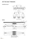
1-3-10.SAF-T-BAR T型電軌(T SERIES CONDUCTOR)
1.C&W電軌系統(SAF-T-BAR)新目錄 1-1.SAF-T-BAR C型電軌(C SERIES CONDUCTOR) 下載down load 1-2.SAF-T-BAR H型電軌(H SERIES CONDUCTOR) 下載down load 1-3.SAF-T-BAR T型電軌(T SERIES CONDUCTOR) 下載down load 1-4.INSUL-8 8字型電軌(INSUL-8 CONDUCTOR) 下載down load 1-5.INSUL-8側向8型電軌(INSUL-8 SIDE CONTACT CONDUCTOR BAR) 下載down load 1-6.CLUSTER電軌CLUSTER BAR 下載down load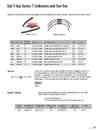
1-3-9.SAF-T-BAR T型電軌(T SERIES CONDUCTOR)
1.C&W電軌系統(SAF-T-BAR)新目錄 1-1.SAF-T-BAR C型電軌(C SERIES CONDUCTOR) 下載down load 1-2.SAF-T-BAR H型電軌(H SERIES CONDUCTOR) 下載down load 1-3.SAF-T-BAR T型電軌(T SERIES CONDUCTOR) 下載down load 1-4.INSUL-8 8字型電軌(INSUL-8 CONDUCTOR) 下載down load 1-5.INSUL-8側向8型電軌(INSUL-8 SIDE CONTACT CONDUCTOR BAR) 下載down load 1-6.CLUSTER電軌CLUSTER BAR 下載down load Collectors with self-lubricating contacts for quiet operation and long life. Multiple collectors will be supplied as single units times the number of phases # Poles Shoe Size Towlines Included? Shoe Matl Recommended For: Cap. Part No. Single Short No Chromium Copper Systems using special towing arrangements 30 A TE301ASCR Single Short Yes Chromium Copper Systems with bend radii tighter than 48" 30 A TE301CR Dual Short Yes Chromium Copper Systems with bend radii tighter than 48" 30 A TE302CR Triple Short Yes Chromium Copper Systems with bend radii tighter than 48" 30 A TE303CR Single Standard Yes Chromium Copper Most systems without tight radii 50A TE501CR Single Standard No Chromium Copper Systems without tight radii 50A TE501ASCR Dual Standard Yes Chromium Most systems without tight radii 50A TE502CR Copper Triple Standard Yes Chromium Copper Systems without tight radii 50A TE503CR The Tow Bar is an optional mounting bracket for Series T collectors. It is designed to mount to a 1" (25.4 mm) square bar and connect to the standard towlines supplied with the Series T collector assemblies. The threaded rod is 18 inches long and is equipped with a clip at each end which provides a connection point for the S-hook at the end of the T-bar towlines. The TB18 will provide the proper angle of pull to ensure smooth travel of the collectors as they are pulled through the rail. TB18 Factory curved conductor sections for applications requiring bends and curves. Please contact factory for further information and pricing. Minimum Bend Radius is 12" *T-Bar curves use different joint clip than the standard straight bar. For Bar Standard Heat Type (PVC) Standard Heat Standard Heat (GRD) (UV) Medium Heat (Lexan) High Heat (Fiberglass) Joint* TA65 TA65X10-CV TA65X10G-CV N/A TA65HHX10-CV N/A TJS100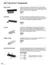
1-3-8.SAF-T-BAR T型電軌(T SERIES CONDUCTOR)
1.C&W電軌系統(SAF-T-BAR)新目錄 1-1.SAF-T-BAR C型電軌(C SERIES CONDUCTOR) 下載down load 1-2.SAF-T-BAR H型電軌(H SERIES CONDUCTOR) 下載down load 1-3.SAF-T-BAR T型電軌(T SERIES CONDUCTOR) 下載down load 1-4.INSUL-8 8字型電軌(INSUL-8 CONDUCTOR) 下載down load 1-5.INSUL-8側向8型電軌(INSUL-8 SIDE CONTACT CONDUCTOR BAR) 下載down load 1-6.CLUSTER電軌CLUSTER BAR 下載down load Connects and aligns standard 10' conductor lengths. Consists of a 4" joint cover that slides over the exposed joint area to complete the insulation. The joint cover locks in place by means of indents and is formed of the same material as the insulating conductor cover. Splice joints are pre-installed on one of complete conductor TJ65 The TF100 is a terminal lug with insulating cover that clamps onto a 3/4" (19.1 mm) length of bare conductor to feed power to the bar. It will accept wires up to # 6 flex. Rated at 100 amperes. The conductor may also be fed by securing a standard terminal lug to the 1/4" hole in the end of the conductor and taping over it for insulation. TF100 End Cap TN100C is a sleeve required to complete the insulation of the conductor. It extends 1/2" (13 mm) over the end of the bar. As an alternative, the conductor may be cut back so that the regular insulating cover extends 1/2" beyond the end of the conductor. End Cap may also be used as a transfer end cap having a ± 1/8" (± 3.2 mm) tolerance with a 1" (25 mm) gap setting on interlocks. TN100C A rigid plastic sleeve, providing 1/2" (13 mm) over-surface gap electrically, for electrical segmentation of conductor bars. A self-supporting sleeve. TA65IS Nylon coated stamped steel hanger clamps. Can be furnished in multiples on 1" (25 mm) centers. Can be mounted using cross bolt or back bolt. Bolts are 1/4" and require a Phase Part No. 1 TH101 2 TH201 3 TH301 4 TH402 5 TH502 5/16" mounting hole. Hangers are required every 5' (1.52 m) of conductor. Joints should be located not more than 3" (76.2 mm) from hangers to avoid flexing. Note: A spool mount insulator hanger option is available as an alternative - Contact Factory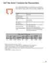
1-3-7.SAF-T-BAR T型電軌(T SERIES CONDUCTOR)
1.C&W電軌系統(SAF-T-BAR)新目錄 1-1.SAF-T-BAR C型電軌(C SERIES CONDUCTOR) 下載down load 1-2.SAF-T-BAR H型電軌(H SERIES CONDUCTOR) 下載down load 1-3.SAF-T-BAR T型電軌(T SERIES CONDUCTOR) 下載down load 1-4.INSUL-8 8字型電軌(INSUL-8 CONDUCTOR) 下載down load 1-5.INSUL-8側向8型電軌(INSUL-8 SIDE CONTACT CONDUCTOR BAR) 下載down load 1-6.CLUSTER電軌CLUSTER BAR 下載down load Series T conductor bars are constructed of roll-formed galvanized steel and are supplied with rail insulation along with the joint kit pre-mounted to one end of the conductor bar. The galvanized steel version provides a current capacity of 65 Amps at 30°C ambient temperature and continuous duty. Description TA65 Material Galvanized Steel Nominal current (Amps) 1 65 DC resistance (ohms/ft) 0.0007 AC Impedance (ohms/ft at 60Hz) 0.0018 Weight 3.0 lb per 10 ft bar(1.36 per 3.05 m bar) Max. Voltage (V) 600 Support Spacing (ft) 5.0 Standard Rail Length (ft) 10 feet - Other lengths on request Maximum Rail Temperature 160OF at 260 PSI (standard cover) 260OF at 260 PSI (high temperature Lexan cover) Conductor Mounting Orientation Can be installed in either vertical or horizontal mode Curves Can be curved in our factory to a 12" (305 mm) minimum radius, using 30 Amp collector shoes. Basic Series T Part Numbers Bar Type TA65 Phase Bar Part No. 2 Ground Bar Part No. 3 Med Heat Bar Part No. 4 Joint Kit Std Heat Part No. 6 Joint Kit Med Heat Lexan Part No. 4 Power Feed Part No. Power Feed Med. Heat Lexan Part No. End Cap Part No. 7 TA65X10 TA65X10G TA65HHX10 TJ65 TJ65HH TF100 TF100HH TN100C 1 Nominal current is based on 30°C and is for 100% duty. 2 Complete with normal phase rail cover, orange rigid PVC, 160°F heat distortion point, 260psi, self extinguishing. 3 Complete with ground rail cover, green rigid PVC, 160°F heat distortion point, 260psi, self extinguishing. 4 Complete with red Lexan medium heat cover, 260°F heat distortion point, 260psi, self extinguishing. 6 Series T conductor kits are provided with the rail joint pre-mounted to the rail. If special cuts are required, use this part number to order the extra joint kit 7 End caps available for "standard heat" applications only.