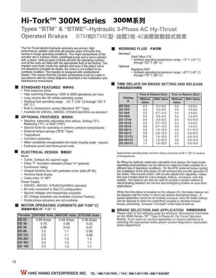
2-18.BTM和BTME油壓-3相AC油壓致動剎車MTM & BTME HYDRAULIC-3PHASE AC HY-THRUST OPERATED BRAKES
 點擊圖片放大
2-18.BTM和BTME油壓-3相AC油壓致動剎車MTM & BTME HYDRAULIC-3PHASE AC HY-THRUST OPERATED BRAKES
2.300M系列鋼廠級鼓式剎車300M Mill Duty Brakes 下載down load
2-3.說明INTRODUCTION
2-4.訂購資料 ORDERING INFORMATION
2-5.訂購資料 ORDERING INFORMATION
2-6.MBE 型直流磁鐵操作剎車
TYPE MBE DC MAGNET OPERATED BRAKES
2-9.MBT 3相AC油壓致動剎車
TYPE MBT 3-PHASE AC HY-THRUST OPERATED BRAKES
2-10.MBT和MBTE 3相AC油壓致動剎車
TYPE MBT & MBTE 3-PHASE AC HY-THRUST OPERATED BRAKES
2-11.MBT和MBTE尺寸和額定能力 MBT & MBTE DIMENSIONS AND RATING
2-12.BM型.油壓(踏板式)剎車Type BM HYDRAULIC (PEDAL) OPERATED BRAKES
2-13.BM型油壓(踏板式)剎車選用和使用 Type BM Selection and Application
2-14.BEM型DC電磁-油壓鼓式剎車
Type BEM DC MAGNETIC-HYDRAULIC OPERATED SHOE BRAKES
2-15.BEM型DC電磁-油壓鼓式剎車
Type BEM DC MAGNETIC-HYDRAULIC OPERATED SHOE BRAKES
2-16.BEM型DC電磁-油壓鼓式剎車尺寸表和額定能力
The Dimensions and Rating of Type BEM SHOE BRAKES
2-17.BTM和BTME油壓-3相AC油壓致動剎車
MTM & BTME HYDRAULIC-3PHASE AC HY-THRUST OPERATED BRAKES
2-18.BTM和BTME油壓-3相AC油壓致動剎車
MTM & BTME HYDRAULIC-3PHASE AC HY-THRUST OPERATED BRAKES
2-19.BTM和BTME油壓致動剎車尺寸表和額定能力
DIMENSIONS & RATING FOR TYPE MTM & BTME AC HY-THRUST BRAKES
2-20.手動油壓剎車系統-BM , BEM , BTM,BTME 型
MANUAL HYDRAULIC BRAKE SYSTEM-TYPE BM , BEM , BTM & MTME BRAKES
2-21.手動油壓剎車系統 MANUAL HYDRAULIC BRAKE SYSTEM
2-22.剎車鼓-ABW型BRAKE WHEELS-TYPE ABW
2-23.聯軸器BRAKE WHEELS COUPLINGS
2-24.聯軸器尺寸表, DIMENSIONS Of BRAKE WHEELS COUPLINGS
2-25.DC電磁剎車整流器和控制器-BE和BEM型
DC MAGNET BRAKE RECTIFIERS/CONTROLLERS
2-26.剎車蓋和保護箱BRAKES COVERS/ENCLOSURES
TheHy吊 lrust electro-hydraulic actualors are proven
cen!rifugalpump and a servo-cylinder wilh apiston. Varioul!lypes of fluids provide ttie operaUng medium
and all the units are filled with the app的priate fluid althelactofY. The motor is nolsubject 10 an
overloadcondition,The impellor is designed with unidireclional blades.This means that the 3-phase cOnnections muslbe made in a∞ordance wlth the wiring diagrams iIIus抽ted in the Installation and Maintenance Instructions.
- STANDARD FEATURES 樣準特性
- Faslresponse times
- Hlgh swilching frequency-120010 2000 operations per hour
(50.C.)Long service IIf,←20million switching cycles
- VVorking Huid operaling range -13.F (﹒鈞。C) through 122.F
- Built in ∞mpressionspring (Standard "8T" Type)
OPTIONA,460VAC,S75VAC/3ph/60Hz as staJ1dard
- Iepless,extemallyadjuslablelimedelays.Sel1lng("S") ,
Releasing , or Both ("HS")
- Special Huids for operatlng In extreme ambient temperalures
- Exlemal torque sprlngs ("BTE" Type)
- Tropicarízed
- Corroslon protection
- Stalor∞mplelelyen臼psulated intomotor housing under vacuum
- Explosion-proof and f1ame-proofunits
- ELECTRICAL DESIGN 電總設計
Motor
- 2-pole,3-phase AC squirrel cage
- Class ' P insulation standard (Class "H" optional)
- Continuous rating
- Inlegral termlnal box with gasketed cover plate (IP 65)
- Terminal block 6-pole
- Cable entry Y: NPT
Power Supply
- 230VAC,460VAC,575VAC/3ph/60Hz standard
- AII uni俗 connected in Star (Y) con訂guration
- SpeciaJ vollages and frequencies available
- DC VOltage actuators are avallable (Contact Factory)
- Single-phase actuators are nolavailable
- MOTOR OPERATING CURRENTS (680 F/200 C)
|
WORKING FLUID 作業流體
Standa
Shell Tellus C10
- Ambienloperating temperature range -13. F (-25. c)
through 122. F (50.C)
Optional
Baysilone M20
- AmbientoIting temperature range -40. F (-40. C)
through 176. F (80'C)
- TIME DELAYS ON BRAKE SETTING AND RELEASE
煞車延遍設定和緣故
Catal09 # | Time to Extend (5ec) | Tíme to Retract (Sec) | ||
Wlthout Valve | Wlth Valve | Wlthout VaJve | Wlth Valve | |
ED 23/5 ED 30/5 ED 50/6 ED 80/6 ED 121/6 ED 201/6 ED 301/6 ED 50/12 ED 80/12 ED 12/12 ED 201/12 。01/ 12 | 0.4 0,4 0.5 0,4 0.4 0.5 0,6 0.8 0.6 0.8 1.0 1.1 | 0.7-6.0 0.5-8,0 0.7-10,0 8.0 8.0 0.7-10,0 0,7-12.0 1,0-16.0 0.9-12,0 1.0-16.0 1.3-20.0 1.6-22.0 | 0.4 0.4 0.4 0.4 0.5 0.4 0.4 0.6 0.5 0.7 0.5 0.5 | 0.6-6.0 0.5-8,0 0.5-8.0 0.4-8.0 0.5-10.0 0.4-8.0 08.4.‘0 0.7-12.0 0.6-10.0 0.8-14.0 0.6-10,0 0.9-10.0 |
Approximate operatlng Umes and t1me delays (seconds) 。f (20' C) work1ng
。tieI mpera this lype if brake Ideal for crane bdges,
olleys,nveyors. and ship loaders,This feature also be used to prode a simple melhod oftheb.issmtl1 action,on-site uslmenlbllily ,makesBy fitting the optlonaJ, extemally adìuslable time delays,the basic brake operating characteristics n be altered 10 make lhe brake suble for a different t ofoting nditions. On the BTE (extemal torque spring) the InsUation of the tìme delay (S) wîll enhance the sm thotion of discminating belween the service and emergency brakes on dualdrive applions.
lypi1 applicatìon WOUld be an inclined nveyor,were the brake release n be delayed to allow the molorlfluid uplíng to develop forward torque、preventing nveyor "run-back" under load alsta.rt-Up.When the time delay is install on the ease (H), the brake release n be delay. until the motor or dve has started developíng to RAKE.SELE:CrIONANDPPLICATol.N
Please refer to the following page for technica,l dimenslonal infomatior on the 300M Series-"BT" Type-3-Phase AC Hy-Thrust Operated Brakes.
If you have an unusual application or rèquire assistance in selecting the appropriate brake please contact Magnetek's Application Sales Dèpartmen
更多商品
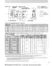
2-19.BTM和BTME油壓致動剎車尺寸表和額定能力DIMENSIONS & RATING FOR TYPE MTM & BTME AC HY-THRUST BRAKES
2.300M系列鋼廠級鼓式剎車300M Mill Duty Brakes 下載down load 2-3.說明INTRODUCTION 2-4.訂購資料 ORDERING INFORMATION 2-5.訂購資料 ORDERING INFORMATION 2-6.MBE 型直流磁鐵操作剎車 TYPE MBE DC MAGNET OPERATED BRAKES 2-9.MBT 3相AC油壓致動剎車 TYPE MBT 3-PHASE AC HY-THRUST OPERATED BRAKES 2-10.MBT和MBTE 3相AC油壓致動剎車 TYPE MBT & MBTE 3-PHASE AC HY-THRUST OPERATED BRAKES 2-11.MBT和MBTE尺寸和額定能力 MBT & MBTE DIMENSIONS AND RATING 2-12.BM型.油壓(踏板式)剎車Type BM HYDRAULIC (PEDAL) OPERATED BRAKES 2-13.BM型油壓(踏板式)剎車選用和使用 Type BM Selection and Application 2-14.BEM型DC電磁-油壓鼓式剎車 Type BEM DC MAGNETIC-HYDRAULIC OPERATED SHOE BRAKES 2-15.BEM型DC電磁-油壓鼓式剎車 Type BEM DC MAGNETIC-HYDRAULIC OPERATED SHOE BRAKES 2-16.BEM型DC電磁-油壓鼓式剎車尺寸表和額定能力 The Dimensions and Rating of Type BEM SHOE BRAKES 2-17.BTM和BTME油壓-3相AC油壓致動剎車 MTM & BTME HYDRAULIC-3PHASE AC HY-THRUST OPERATED BRAKES 2-18.BTM和BTME油壓-3相AC油壓致動剎車 MTM & BTME HYDRAULIC-3PHASE AC HY-THRUST OPERATED BRAKES 2-19.BTM和BTME油壓致動剎車尺寸表和額定能力 DIMENSIONS & RATING FOR TYPE MTM & BTME AC HY-THRUST BRAKES 2-20.手動油壓剎車系統-BM , BEM , BTM,BTME 型 MANUAL HYDRAULIC BRAKE SYSTEM-TYPE BM , BEM , BTM & MTME BRAKES 2-21.手動油壓剎車系統 MANUAL HYDRAULIC BRAKE SYSTEM 2-22.剎車鼓-ABW型BRAKE WHEELS-TYPE ABW 2-23.聯軸器BRAKE WHEELS COUPLINGS 2-24.聯軸器尺寸表, DIMENSIONS Of BRAKE WHEELS COUPLINGS 2-25.DC電磁剎車整流器和控制器-BE和BEM型 DC MAGNET BRAKE RECTIFIERS/CONTROLLERS 2-26.剎車蓋和保護箱BRAKES COVERS/ENCLOSURESApproximate Dímensíons in Inches 近似尺寸(爽的) B。RAKE-WHEEl A B c E F G J K L M N p Q R T u v 5" (2) 8" 10" 13" 16" 19" 4_19 3.25 4.00 5.75 7.50 9.25 2.44 2.88 3.13 4.50 5.38 2.75 3.25 3.75 5.75 6.75 0.44 0.69 0.69 0.81 1.06 1.06 4.06 70. 0 8.38 9.88 12.13 13.25 6.38 6.38 6.38 7.75 9.50 9.50 0.63 0.75 0 .88 1.00 1.25 1.75 5.88 7.25 8.00 11.00 13.25 15.63 6.00 7.25 9.88 12.50 15.25 20.25 16.00 18.00 22.00 24.00 30.00 33.00 4.50 5.38 5.88 8.56 10.00 13.00 0.50 0.75 0.75 0.88 1.00 1.13 8.19 11.31 13.00 16.00 17.69 20.50 7.69 12.63 15.44 19.00 23.06 26.25 15.50 1 5.50 19.13 23.13 31.75 33.00 4.69 6.88 8.35 10.84 13.63 18.50 4.56 7.00 8.63 11.25 13.88 16.63 2.88 3.00 3.00 3.63 3.63 3.63 6.50 8.75 Ratings Data AISE-NEMA and General Purpose (Heavy Duty) Fitted with molded non-asbestos linings AI-NEMA初一般用途額定數總 RATINGS SHOWN FOR CONTlNUOUS OPERATlON OF ACTUATOR THE TORQUE RATINGS APPLY AT A WORN LlNiNG CONDITlON DEFINED AS THE POINT WHERE THE BRAKE RE-AOJUSTS.OR WHERE ADJUSTMENT IS REQUIREO AS RECOMMENDED BY THE BRAKE OPERATING INSTRUCTIONS.(3) ForHy-TI、51Actualor da refer 10 ihe Appllcalion and Englneerìng Pa1a section(2) AISNEMA does nOIdefine a 5.inct s;xe brai<e.(1) Servir。parkìng IOrque. Brake selection is based on lorque and duty. When brakìng se l'lllce Is severe. he Wof ihe load speed ofIhe bJ<ewheel and maximum number 01slops per mi le should be submltled 10 Ihe factory for re mmendatton.For seleclìon and appll tìon da refer 10 lhe Application and Engineerlng Oala section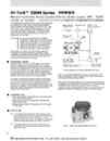
2-20.手動油壓剎車系統-BM , BEM , BTM,BTME 型MANUAL HYDRAULIC BRAKE SYSTEM-TYPE BM , BEM , BTM & MTME BRAKES
2.300M系列鋼廠級鼓式剎車300M Mill Duty Brakes 下載down load 2-3.說明INTRODUCTION 2-4.訂購資料 ORDERING INFORMATION 2-5.訂購資料 ORDERING INFORMATION 2-6.MBE 型直流磁鐵操作剎車 TYPE MBE DC MAGNET OPERATED BRAKES 2-9.MBT 3相AC油壓致動剎車 TYPE MBT 3-PHASE AC HY-THRUST OPERATED BRAKES 2-10.MBT和MBTE 3相AC油壓致動剎車 TYPE MBT & MBTE 3-PHASE AC HY-THRUST OPERATED BRAKES 2-11.MBT和MBTE尺寸和額定能力 MBT & MBTE DIMENSIONS AND RATING 2-12.BM型.油壓(踏板式)剎車Type BM HYDRAULIC (PEDAL) OPERATED BRAKES 2-13.BM型油壓(踏板式)剎車選用和使用 Type BM Selection and Application 2-14.BEM型DC電磁-油壓鼓式剎車 Type BEM DC MAGNETIC-HYDRAULIC OPERATED SHOE BRAKES 2-15.BEM型DC電磁-油壓鼓式剎車 Type BEM DC MAGNETIC-HYDRAULIC OPERATED SHOE BRAKES 2-16.BEM型DC電磁-油壓鼓式剎車尺寸表和額定能力 The Dimensions and Rating of Type BEM SHOE BRAKES 2-17.BTM和BTME油壓-3相AC油壓致動剎車 MTM & BTME HYDRAULIC-3PHASE AC HY-THRUST OPERATED BRAKES 2-18.BTM和BTME油壓-3相AC油壓致動剎車 MTM & BTME HYDRAULIC-3PHASE AC HY-THRUST OPERATED BRAKES 2-19.BTM和BTME油壓致動剎車尺寸表和額定能力 DIMENSIONS & RATING FOR TYPE MTM & BTME AC HY-THRUST BRAKES 2-20.手動油壓剎車系統-BM , BEM , BTM,BTME 型 MANUAL HYDRAULIC BRAKE SYSTEM-TYPE BM , BEM , BTM & MTME BRAKES 2-21.手動油壓剎車系統 MANUAL HYDRAULIC BRAKE SYSTEM 2-22.剎車鼓-ABW型BRAKE WHEELS-TYPE ABW 2-23.聯軸器BRAKE WHEELS COUPLINGS 2-24.聯軸器尺寸表, DIMENSIONS Of BRAKE WHEELS COUPLINGS 2-25.DC電磁剎車整流器和控制器-BE和BEM型 DC MAGNET BRAKE RECTIFIERS/CONTROLLERS 2-26.剎車蓋和保護箱BRAKES COVERS/ENCLOSURES The 300M Pedal Controlled Manual Hydraulic Brake Systems are designed for he BM Type Hydraulìc Brake,the BEM Type DC Magnet Operated Brake and the BTM/BTME Type 3-phase AC Thruster Operaed Brake models.In all ses, the hydraulic portion functions in he same manner and utilizes the same basic components. The syslem provides crane operators wlth a smooth melhod 01slowlng and slopplng the crane bridge. The following is a list 01the manual systems avaUable: 口 Slngle brake, single station,wilh manual bleed 口 Single brake, single station,wilh remole bleed 口 Dual brake,single station, with manual bleed o Dual brake. two slation. wilh remole bleed 口 Slngle brake, two station,with remole bleed o Dual brake. two saion,with remole bleed Each brake kit contains all he components,ubing and miscellaneous hardware required 10 complete a normal installatlon.The Manual Hydraulic Brake System Kit must be ordered individually: they are nol included wilh he brake assemblies and wheel (slave) cylínders. OPERATION 操作說明 Mechanical force applied 10 he rOOIpedal Is converted 10 hydraulic pressure by he master cylinder. This hydraulic pressure ís transmi!ted via Ihe connecting línes 10 the brake wheel (slave) cylinde,r which ín tum operates Ihe brake. The pressure developed by the masler cyllnder is proportional 10 the force applled 10 Ihe 1001 pedal. Thus the pedallmasler cylinder assembly provides a control lhalls Inf1nilely variable between zero andIhe maximum torce/torque rating. A provislon Is made in all systems 10 keep Ihe back end of the wheel (slave) cylinders f1l1ed wlth fluid. The lni e for thìs purpose connecls 10 a“ tee" in lhe line leadíng from Ihe reservoir 10 the master cylinder. Keeping the back end 01Ihe wheel (slave) cylinders filled wi th nuid provides lubri tìon for the pìston,reduces contamination and prevents air from beíng drawn past the piston. FEATURES 特性 Short brake pedal for full braklng power through Ihe use of a dual action master cylinder Maximum of 70 pounds of pedal force (Complles with OSHA requirernents) Standard manual system can operale up 102-16" brakes or 1-19 brake NOTES 傷詮 The maximum líne length from masler cylinder 10 the wheel (slave) cylinder should nolexceed 150 feel(Ienglh of pressurtzed syslemlubíng一→one way). In a dual brake/one stíon system,the líne length from Ihe master cyllnder 10 each wheel (slave) Is IImited 10150 feet. o The wheelcyllnder and the masler cyllnder must be compatible with respect 10 the Iype of brake f1uid Ihat each syslem uses.OPTlONAL REMOTE BLE印ER MASTER 釘州ONMANUAL KIT PEOAL OPERATED TYPICAL MANUAL HYDRAULlC BRAKE SYSTEMS The manual system lIIustrated above shows a single brake,one station arrangement with the standard manual bleed.The optional remote control bleed is shown doted. The remote ontrol bleed system permits qulck and easy bleeding of the syslem by Ihe crane operator trom the cab.The system consists of a fluid reservoir. a solenoid-operaled conlrol valve and a pushbutton swìlch which operates lhe valve. The pushbutton switch should be installed in a localion convenient 10 Ihe crane operator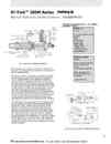
2-21.手動油壓剎車系統 MANUAL HYDRAULIC BRAKE SYSTEM
2.300M系列鋼廠級鼓式剎車300M Mill Duty Brakes 下載down load 2-3.說明INTRODUCTION 2-4.訂購資料 ORDERING INFORMATION 2-5.訂購資料 ORDERING INFORMATION 2-6.MBE 型直流磁鐵操作剎車 TYPE MBE DC MAGNET OPERATED BRAKES 2-9.MBT 3相AC油壓致動剎車 TYPE MBT 3-PHASE AC HY-THRUST OPERATED BRAKES 2-10.MBT和MBTE 3相AC油壓致動剎車 TYPE MBT & MBTE 3-PHASE AC HY-THRUST OPERATED BRAKES 2-11.MBT和MBTE尺寸和額定能力 MBT & MBTE DIMENSIONS AND RATING 2-12.BM型.油壓(踏板式)剎車Type BM HYDRAULIC (PEDAL) OPERATED BRAKES 2-13.BM型油壓(踏板式)剎車選用和使用 Type BM Selection and Application 2-14.BEM型DC電磁-油壓鼓式剎車 Type BEM DC MAGNETIC-HYDRAULIC OPERATED SHOE BRAKES 2-15.BEM型DC電磁-油壓鼓式剎車 Type BEM DC MAGNETIC-HYDRAULIC OPERATED SHOE BRAKES 2-16.BEM型DC電磁-油壓鼓式剎車尺寸表和額定能力 The Dimensions and Rating of Type BEM SHOE BRAKES 2-17.BTM和BTME油壓-3相AC油壓致動剎車 MTM & BTME HYDRAULIC-3PHASE AC HY-THRUST OPERATED BRAKES 2-18.BTM和BTME油壓-3相AC油壓致動剎車 MTM & BTME HYDRAULIC-3PHASE AC HY-THRUST OPERATED BRAKES 2-19.BTM和BTME油壓致動剎車尺寸表和額定能力 DIMENSIONS & RATING FOR TYPE MTM & BTME AC HY-THRUST BRAKES 2-20.手動油壓剎車系統-BM , BEM , BTM,BTME 型 MANUAL HYDRAULIC BRAKE SYSTEM-TYPE BM , BEM , BTM & MTME BRAKES 2-21.手動油壓剎車系統 MANUAL HYDRAULIC BRAKE SYSTEM 2-22.剎車鼓-ABW型BRAKE WHEELS-TYPE ABW 2-23.聯軸器BRAKE WHEELS COUPLINGS 2-24.聯軸器尺寸表, DIMENSIONS Of BRAKE WHEELS COUPLINGS 2-25.DC電磁剎車整流器和控制器-BE和BEM型 DC MAGNET BRAKE RECTIFIERS/CONTROLLERS 2-26.剎車蓋和保護箱BRAKES COVERS/ENCLOSURES The complele master cylinder assembly. as shown in Fig. 2 consÎsts of: the master cylinde,r a foolpeda,l a mounting base and Ihe operating línkage. The master cylinder is a two-stage unit. containing one large diameter piston and one smaller diameter piston (Reference Fìg. 2).Thelarge diameter piston displaces a substantial volume of fluid wlth a relailvely small amount of 100t pedal lravel. ThÎs volume of 11uid is forced oulthrough the passage in Ihe fixed pislon rod loIhe wheel cyllnder and quickly moves Ihe brake shoes Inlo conlaclwilh the brake wheel. Resislance 10 fu付ler movement of the shoe causes pressure 10 bulld in lhe sys em.This pressure Is sensed 1n the metered relief valve. At a predelermined pressure level. the relief valve Iffts off ils lower sea,l venilng the lower pressure chamber lnto the reservolr chamber. High pressure exlsls 1n the high pressure cylinder chamber and the low pressure cup flares out and seals against Ihe walls of the high pressure cylinder chamber. The small pislon ls now up against Ihe end of the tixed pislon rod. and conljnued movemenlof the large píston effectively shortens he length in height of the high-pressure cylinder chamber. The pressure in Ihis chamber increases as he chamber volume decreases and is Iransmitled through lhe fixed piston rod passage and out to the brake wheel cylínder. Due 10 the smaller area on Ihe piston,pressure developed wilh a glven amounlof fOOIpedal forceis much grealer than pressure developed by the large pislon,In summary,Ihe large diameter piston serves 10 move Ihe brake shoes rapidly into con旬Clwilh Ihe brake wheel whiie using up little of the lolal pedal travel. The small piston serves 10 develop high pressure for positive braking.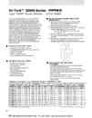
2-22.剎車鼓-ABW型BRAKE WHEELS-TYPE ABW
2.300M系列鋼廠級鼓式剎車300M Mill Duty Brakes 下載down load 2-3.說明INTRODUCTION 2-4.訂購資料 ORDERING INFORMATION 2-5.訂購資料 ORDERING INFORMATION 2-6.MBE 型直流磁鐵操作剎車 TYPE MBE DC MAGNET OPERATED BRAKES 2-9.MBT 3相AC油壓致動剎車 TYPE MBT 3-PHASE AC HY-THRUST OPERATED BRAKES 2-10.MBT和MBTE 3相AC油壓致動剎車 TYPE MBT & MBTE 3-PHASE AC HY-THRUST OPERATED BRAKES 2-11.MBT和MBTE尺寸和額定能力 MBT & MBTE DIMENSIONS AND RATING 2-12.BM型.油壓(踏板式)剎車Type BM HYDRAULIC (PEDAL) OPERATED BRAKES 2-13.BM型油壓(踏板式)剎車選用和使用 Type BM Selection and Application 2-14.BEM型DC電磁-油壓鼓式剎車 Type BEM DC MAGNETIC-HYDRAULIC OPERATED SHOE BRAKES 2-15.BEM型DC電磁-油壓鼓式剎車 Type BEM DC MAGNETIC-HYDRAULIC OPERATED SHOE BRAKES 2-16.BEM型DC電磁-油壓鼓式剎車尺寸表和額定能力 The Dimensions and Rating of Type BEM SHOE BRAKES 2-17.BTM和BTME油壓-3相AC油壓致動剎車 MTM & BTME HYDRAULIC-3PHASE AC HY-THRUST OPERATED BRAKES 2-18.BTM和BTME油壓-3相AC油壓致動剎車 MTM & BTME HYDRAULIC-3PHASE AC HY-THRUST OPERATED BRAKES 2-19.BTM和BTME油壓致動剎車尺寸表和額定能力 DIMENSIONS & RATING FOR TYPE MTM & BTME AC HY-THRUST BRAKES 2-20.手動油壓剎車系統-BM , BEM , BTM,BTME 型 MANUAL HYDRAULIC BRAKE SYSTEM-TYPE BM , BEM , BTM & MTME BRAKES 2-21.手動油壓剎車系統 MANUAL HYDRAULIC BRAKE SYSTEM 2-22.剎車鼓-ABW型BRAKE WHEELS-TYPE ABW 2-23.聯軸器BRAKE WHEELS COUPLINGS 2-24.聯軸器尺寸表, DIMENSIONS Of BRAKE WHEELS COUPLINGS 2-25.DC電磁剎車整流器和控制器-BE和BEM型 DC MAGNET BRAKE RECTIFIERS/CONTROLLERS 2-26.剎車蓋和保護箱BRAKES COVERS/ENCLOSURES The ABW Type Brake Wheels are manufactured from specially formulated ductile-iron alloy 臼 stings.This material has great strength. good machlnability and is resistant to scoring. It Is ∞mpatible with a variety of friction materials,where as the IIning and the brake wheel wear evenly and smoothly. Fully machined wheels can be supplied with a parallel or tapered bore and keyway to meet the customer's specifications.Tapered bored hubs can be provided with a bent lock washer slot to give a more positive method of locking the wheel to the shaft. The wheels can be furnished completely machined 10 provide proper balance at normal operating speds. Brake wheels can also be furnished semi-finished with a solid or rough bored hub for tinal machining by the customer. Standard wheel dimensions are shown on the table below; wheels that do not fall wilhln these dimensional parameters may slill be avaìlable,please contact the factory. STANDARD FEATυRES 線畫展特性 Manufactured from ductile-Iron alloy Completely machined 10 provide proper balance at normal operating speeds. Resistanl10 scoring Wears smoothly and evenly Good ∞mpalibilltywilh friction materials OPTIONAL FEATURES 選用特性 Parallel bore and keyway Tapered bore and keyway Lock washer slol Speclal materials,1001stee,l etc. Deep rburizlhg Chrome plated brake path DynamÎc balancing Non-destructive testìng Brake wheel couplings SELECTING BRAKE WHEEL HUB OFFSET 1. Start from the wheel centerlne and determine offset dimension "0" within Ihe maximum and minimum dimensions provided in table below. Determine hub length, dimensìon "E" required. Use the followlng formula to see if dimension "F" value falls within the limits provided in the table below. 4, Ifthe . dìmension does not fall within Ihe limits provided In the table. change dimension "0" wlthin limits provided ln the table."X" = "E" - "0" (may be a pos. or neg. value) "F" (1/2"C")- “X. avaìlability,Note that more than one wheel pattem Is avail.5. Wheels thaldo not fall within the limits provided In the table below must be checked wiU Ihe factory for cost and BORE AND KEYWAY MACHINING For machining wheel bores and keyways.please provide complete shaft dimenslonal data. For tapered shafts. don't forget the "taper per fool" data For parallel bores provide complete keyway dimenslons and advise if gib key or keeper plate wìll be used to hold the wheel 10 the shaft ,For standard AISE-NEMA DC or AC wound rotor motors ,only the motor information is required• For non-standard motors and special wheels, please conlact taclory. Rating Data and Approximate Dimensions /Weights WHEEl DIAMETER IN. WHEEl WIDTH 'C' JN. HUB DJAMETER 'S' IN. 旬' OFFSET ' F' MAXBORE RECOMMENDED IN. MAX SPEED R.P.M. WK' (APPROX) LB.FT.' WEIGHT (APPROX) LBS. MAX IN. I JN. N MAX JN. MJN IN. 5" (1) 2.75 3,13 3.00 1.37 1.37 0.812 2.00 9400 0.25 7 8" 3.25 3,75 4.88 2.00 2.37 1.12 2.00 5870 1.25 20 10" 3.75 4.75 5.00 2.75 2.62 1.87 2.50 4700 2.80 34 13" 5,75 6.75 6.25 3.12 4.25 1.62 4.75 3600 12.00 75 16" 6.75 6.75 6.50 3.37 5.00 2.62 4.00 2940 29.50 115 19" 8,75 7.00 7.50 5.50 7.50 5.62 4.62 2470 74.20 180 23" 11.25 9.50 8.88 5.25 7.88 5.50 5,00 2040 155.60 305 30" 14.25 13.50 12.75 9.50 12,75 7.13 7.00 1340 880.00 980
2-23.聯軸器BRAKE WHEELS COUPLINGS
2.300M系列鋼廠級鼓式剎車300M Mill Duty Brakes 下載down load 2-3.說明INTRODUCTION 2-4.訂購資料 ORDERING INFORMATION 2-5.訂購資料 ORDERING INFORMATION 2-6.MBE 型直流磁鐵操作剎車 TYPE MBE DC MAGNET OPERATED BRAKES 2-9.MBT 3相AC油壓致動剎車 TYPE MBT 3-PHASE AC HY-THRUST OPERATED BRAKES 2-10.MBT和MBTE 3相AC油壓致動剎車 TYPE MBT & MBTE 3-PHASE AC HY-THRUST OPERATED BRAKES 2-11.MBT和MBTE尺寸和額定能力 MBT & MBTE DIMENSIONS AND RATING 2-12.BM型.油壓(踏板式)剎車Type BM HYDRAULIC (PEDAL) OPERATED BRAKES 2-13.BM型油壓(踏板式)剎車選用和使用 Type BM Selection and Application 2-14.BEM型DC電磁-油壓鼓式剎車 Type BEM DC MAGNETIC-HYDRAULIC OPERATED SHOE BRAKES 2-15.BEM型DC電磁-油壓鼓式剎車 Type BEM DC MAGNETIC-HYDRAULIC OPERATED SHOE BRAKES 2-16.BEM型DC電磁-油壓鼓式剎車尺寸表和額定能力 The Dimensions and Rating of Type BEM SHOE BRAKES 2-17.BTM和BTME油壓-3相AC油壓致動剎車 MTM & BTME HYDRAULIC-3PHASE AC HY-THRUST OPERATED BRAKES 2-18.BTM和BTME油壓-3相AC油壓致動剎車 MTM & BTME HYDRAULIC-3PHASE AC HY-THRUST OPERATED BRAKES 2-19.BTM和BTME油壓致動剎車尺寸表和額定能力 DIMENSIONS & RATING FOR TYPE MTM & BTME AC HY-THRUST BRAKES 2-20.手動油壓剎車系統-BM , BEM , BTM,BTME 型 MANUAL HYDRAULIC BRAKE SYSTEM-TYPE BM , BEM , BTM & MTME BRAKES 2-21.手動油壓剎車系統 MANUAL HYDRAULIC BRAKE SYSTEM 2-22.剎車鼓-ABW型BRAKE WHEELS-TYPE ABW 2-23.聯軸器BRAKE WHEELS COUPLINGS 2-24.聯軸器尺寸表, DIMENSIONS Of BRAKE WHEELS COUPLINGS 2-25.DC電磁剎車整流器和控制器-BE和BEM型 DC MAGNET BRAKE RECTIFIERS/CONTROLLERS 2-26.剎車蓋和保護箱BRAKES COVERS/ENCLOSURES BRAKE WHEEL COUPLlNGS 煞建設聯軍自認 The brake wheel couplings are available for all 300M Series shoe brakes. They are useful in situations where space is limited and also eliminale the need for expensive double shaft extensions on motors and gearboxes. SELECTION 選擇用途 Torque ratings Ilsted are Iypical values for Ihe 300M Seríes brakes based on normal operatlon of Ihe drive syslems. For repelilíve hígh peak load applícatíons please contact Ihe factory. Maximum speeds (RPM) are based on Ihe maximum RIM velocíty of 6000 feelper minule. Brake wheels and couplíngs muslbe balanced if perípheral speeds exceed his value. Couplings are normally furníshed wilh an average inlerference filof 0.0005" per inch of shaft diamele,r unless otherwise specified. Double engagement brake wheel couplings requi 的 realignmenlof Ihe brake wheel 10 Ihe brake if parallel misalignmenlbecomes excessive due 10 ílting of wheel and sleeve assembly. The high Ugalforces en∞untered In ∞uplings separale the base oíl and Ihickener of general-pu巾ose. Speclal long-term grease (LTG) onJy should be used. Standardcoupling seaJs are BUNA-N ma erial. Maximum continuous operating lemperalure is 250'F (121'C) and maximum intermittent (Iess than 1000 hours) operallng lemperature is 300. F (1490 C). For unlisled brake torques and couplíng types,please consult Ihe factory.• Melric sizes are oplional. BRAKE WHEEL COUPLlNG ORDERING INFORMATION 煞車111車自認訂購資料 1) Specify coupllng (If selecting from the s!andard unlts shown on 內. 26 simply specify t怕也talog number. Example 13" x 5.75" -1025G) or íf nolknown please supply Ihe fOllowlnginformation: Brake wheel diameter and fa 個 widlh Molor HP and RPM (or speed) of shaft Ihat the brake wheel ís to be mounled Gear ratío or shaft speeds Delails of Ihe appli叫 ion 2) Specify hub bores and keyway dimensions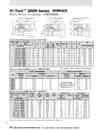
2-24.聯軸器尺寸表, DIMENSIONS Of BRAKE WHEELS COUPLINGS
2.300M系列鋼廠級鼓式剎車300M Mill Duty Brakes 下載down load 2-3.說明INTRODUCTION 2-4.訂購資料 ORDERING INFORMATION 2-5.訂購資料 ORDERING INFORMATION 2-6.MBE 型直流磁鐵操作剎車 TYPE MBE DC MAGNET OPERATED BRAKES 2-9.MBT 3相AC油壓致動剎車 TYPE MBT 3-PHASE AC HY-THRUST OPERATED BRAKES 2-10.MBT和MBTE 3相AC油壓致動剎車 TYPE MBT & MBTE 3-PHASE AC HY-THRUST OPERATED BRAKES 2-11.MBT和MBTE尺寸和額定能力 MBT & MBTE DIMENSIONS AND RATING 2-12.BM型.油壓(踏板式)剎車Type BM HYDRAULIC (PEDAL) OPERATED BRAKES 2-13.BM型油壓(踏板式)剎車選用和使用 Type BM Selection and Application 2-14.BEM型DC電磁-油壓鼓式剎車 Type BEM DC MAGNETIC-HYDRAULIC OPERATED SHOE BRAKES 2-15.BEM型DC電磁-油壓鼓式剎車 Type BEM DC MAGNETIC-HYDRAULIC OPERATED SHOE BRAKES 2-16.BEM型DC電磁-油壓鼓式剎車尺寸表和額定能力 The Dimensions and Rating of Type BEM SHOE BRAKES 2-17.BTM和BTME油壓-3相AC油壓致動剎車 MTM & BTME HYDRAULIC-3PHASE AC HY-THRUST OPERATED BRAKES 2-18.BTM和BTME油壓-3相AC油壓致動剎車 MTM & BTME HYDRAULIC-3PHASE AC HY-THRUST OPERATED BRAKES 2-19.BTM和BTME油壓致動剎車尺寸表和額定能力 DIMENSIONS & RATING FOR TYPE MTM & BTME AC HY-THRUST BRAKES 2-20.手動油壓剎車系統-BM , BEM , BTM,BTME 型 MANUAL HYDRAULIC BRAKE SYSTEM-TYPE BM , BEM , BTM & MTME BRAKES 2-21.手動油壓剎車系統 MANUAL HYDRAULIC BRAKE SYSTEM 2-22.剎車鼓-ABW型BRAKE WHEELS-TYPE ABW 2-23.聯軸器BRAKE WHEELS COUPLINGS 2-24.聯軸器尺寸表, DIMENSIONS Of BRAKE WHEELS COUPLINGS 2-25.DC電磁剎車整流器和控制器-BE和BEM型 DC MAGNET BRAKE RECTIFIERS/CONTROLLERS 2-26.剎車蓋和保護箱BRAKES COVERS/ENCLOSURESApproximate Dimensions (inches) 近似尺寸(美的) AB x JB I REF c L " MA MB MAX MC MD MAX NB FIG 可 & 3 NB FIG 2 NC ZD ZE GAP CATALOG# 們G1 FIG 2 & 3 8 X3.25 - 1015G 10 X 3.75 -1015G 可 3 X 5.75 -1020G 13 X 5.75 -1025G 可 6 X 6.75 -1025G 19 X 8.75 -1030G 19 X 8.75 - 1035G 23 X 11.25 -1040G 23 X 司1 25 -1040G 30 X 14.25 - 1050G 30 X 14.25 - 1050G 1.94 1.94 2.44 3.03 3.03 3.59 4.19 4.75 4.75 6.03 6.03 1.82 1.82 2.30 2.90 2.90 3.46 4.02 4.54 4.54 5.80 5.80 2.40 2.40 3.00 3.60 3.60 4.20 5.10 5.70 5.70 7.20 7.20 4.50 5.00 5.62 625 6.38 7.00 7.12 8.20 8.31 8.50 9.62 2.90 2.90 3.50 4.10 4.72 5.88 6.58 7.82 8.26 10.63 9.76 0.56 0.88 0.75 1.12 。25. 0.12 0.00 0.44' 0.44' 44.00 0.61 0.92 0.80 1.14 0.14 0.23 0.12 0.05 39.00 37.00' 37.00' 1.47 2.03 2.91 3.19 2.69 3.31 3.47 4.59 4.16 5.38 6.00 0.94 1.00 1.13 1.25 1.38 1.50 1.63 1.75 1.31 1.75 2.37 3.00 3.50 4.00 4.50 4.5再 5.00 5.00 5.50 6.00 6.75 7.75 0.625 0.625 0.625 0.750 0.750 0.750 1.000 1.000 1.000 1.312 1.312 0.660 0.660 。0.660 .750 0.750 0.750 0.980 1.050 1.050 1.360 1.360 Maximum Operating Misalignment 續六線作失線(沒對正} For construction purposes request certified drawing SIZE DOUBLE ENGAGEMENT SINGLE ENGAGEMENT P。ARALLEL INCHES ANGULAR PARALLEL OFFSET INCHES ANGULAR INCHES DEGREES INCHES DEGREES '5G 1020G 1025G 1030G 1035G 1040G 1050G 0.005 0.010 0.010 0.012 0.012 0.012 0.012 0.005 0.010 0.010 0.015 0.015 0.020 0.020 1 /4 1 /4 1 /4 1 /4 1 /4 1 /4 1 /4 00 Not Use Single EngagemenlCoupllngs 10 Compensate For Parallel Offset Mlsalìgnment 0.005 0.010 0.010 0.015 0.015 0.020 0.020 1f8 118 118 1 /8 118 118 1/8 Maximum Operating Misalignment BR。AKEWHEEL AB JB COUPLlNG REF. BRAKE RATING (也.FT.) MILL MOTOR SIZE MAX SPEED RPM MIN BORE (1) WEIGHTLBS. WK'(LB.FT.) WHEEL AND COUPLlNG LUBE WHEEL AND COUPLlNG COUPLlN. G (NO BORE) CATALOG# 8 X 3.25 -1015G 10 X 3.75 - 1015G 13 X 5.75 - 1020G 13 X 5.75 -1025G 16 X 6.75 - 1025G 可 9 X 8.75 -1030G 19 X 8,75 -1035G 23 X 11.25 - 1040G 23 X 11.25 - G。 30 X 14.25 . 1050G 30 X 14.25. 1050G 100 200 550 550 1000 2000 2000 4000 4000 9000 9000 2,602 603.604 606 608 610 612 614 616 618 620 622 2860 2290 1760 1760 1430 1200 1200 995 995 765 765 0.75 0.75 1.00 1.25 1.25 1.50 2.00 2.50 2.50 3.50 3.50 33 40 80 110 170 170 225 390 390 900 900 0.20 0.20 0.30 0.60 0.60 0.90 1.25 2.00 2.00 4.12 4.12 1.4 3.5 13.1 14.7 33.0 81.0 87.0 230.0 230.0 700.0 700.0 0.486 0.486 1.040 2.680 2.680 4.900 11.300 21.600 21 600 62.500 62.500 (1) For bores less lhan mlnlmum values shown above ∞nsult factory (Flexible and Rigîó HUb).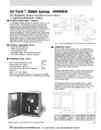
2-25.DC電磁剎車整流器和控制器-BE和BEM型DC MAGNET BRAKE RECTIFIERS/CONTROLLERS
2.300M系列鋼廠級鼓式剎車300M Mill Duty Brakes 下載down load 2-3.說明INTRODUCTION 2-4.訂購資料 ORDERING INFORMATION 2-5.訂購資料 ORDERING INFORMATION 2-6.MBE 型直流磁鐵操作剎車 TYPE MBE DC MAGNET OPERATED BRAKES 2-9.MBT 3相AC油壓致動剎車 TYPE MBT 3-PHASE AC HY-THRUST OPERATED BRAKES 2-10.MBT和MBTE 3相AC油壓致動剎車 TYPE MBT & MBTE 3-PHASE AC HY-THRUST OPERATED BRAKES 2-11.MBT和MBTE尺寸和額定能力 MBT & MBTE DIMENSIONS AND RATING 2-12.BM型.油壓(踏板式)剎車Type BM HYDRAULIC (PEDAL) OPERATED BRAKES 2-13.BM型油壓(踏板式)剎車選用和使用 Type BM Selection and Application 2-14.BEM型DC電磁-油壓鼓式剎車 Type BEM DC MAGNETIC-HYDRAULIC OPERATED SHOE BRAKES 2-15.BEM型DC電磁-油壓鼓式剎車 Type BEM DC MAGNETIC-HYDRAULIC OPERATED SHOE BRAKES 2-16.BEM型DC電磁-油壓鼓式剎車尺寸表和額定能力 The Dimensions and Rating of Type BEM SHOE BRAKES 2-17.BTM和BTME油壓-3相AC油壓致動剎車 MTM & BTME HYDRAULIC-3PHASE AC HY-THRUST OPERATED BRAKES 2-18.BTM和BTME油壓-3相AC油壓致動剎車 MTM & BTME HYDRAULIC-3PHASE AC HY-THRUST OPERATED BRAKES 2-19.BTM和BTME油壓致動剎車尺寸表和額定能力 DIMENSIONS & RATING FOR TYPE MTM & BTME AC HY-THRUST BRAKES 2-20.手動油壓剎車系統-BM , BEM , BTM,BTME 型 MANUAL HYDRAULIC BRAKE SYSTEM-TYPE BM , BEM , BTM & MTME BRAKES 2-21.手動油壓剎車系統 MANUAL HYDRAULIC BRAKE SYSTEM 2-22.剎車鼓-ABW型BRAKE WHEELS-TYPE ABW 2-23.聯軸器BRAKE WHEELS COUPLINGS 2-24.聯軸器尺寸表, DIMENSIONS Of BRAKE WHEELS COUPLINGS 2-25.DC電磁剎車整流器和控制器-BE和BEM型 DC MAGNET BRAKE RECTIFIERS/CONTROLLERS 2-26.剎車蓋和保護箱BRAKES COVERS/ENCLOSURES AC STATIC RECTIFIERS The AC Static/Rec ifier Controller is designed 10 operate the BE and BEM Type,AISE-NEMA shunt wound 50 volt DC shoe brakes installed on AC powered equipment. The basic unit consists of a multi-tapped power transformer,bridge rectifier, contactor,statlc control PCB and a protective circuit breaker,all CON iROl CIRCUI1 mounted on a steel backing plate for pan自I mounting on customer's equipment. The unit is designed with a slalicliming ÀC CONNEC r'ON circui,l which elìminates relay conlacls. The economizing circuil reduces power ∞nsumptlon and assures fast brake release when power is removed. The forcing circullassures faslbrake release when Ihe power is initially applied 10 the brake. AII models are equipped with a multi-tapped p吋mary lransformer for 230V, 460V and 575V slngle-phase power supplies. OPTIONAL FEATURES NEMA-Type 3R Enclosures NEMA-Type 4 Enclosures Anli-condensation healer Timedelay (Diode→llounted Inside enclosure) Timedelay (Adjustable-customer mounted) ORDERING CODE Brake Controller Designation-ABC Quantity and Síze of Brakes Type of Enclosure-(3R or 4) Power Supply 230, 460, 575 VAC/3Ph/60Hz Designates an AC Statíc Reclifier to control a single 10" MBE Brake in a NEMA 3R Enclosure from a 460V/60Hz power supply. OPERATION 操作說明 The static rectlfier/controller shown in Fig. 1 is equipped with two eleclronlccircuits one for releasing Ihe brakes quicl<ly (forcin9) and energizing the brake ∞i1.When the AC vol is applied 10 thereclifiers (diod) 10 nvert AC inpul10 a full wave DC output forthe olher for maintaining the brakes In the released position.The system utilizes silicon ntrolled rec (SCR's) and sili n ∞ntrol system. the brake relay (BR) is eneized and the two SCR's ∞nduct on allemawe half cycles.Thls results in approximalely 100 volts being applied to the brake coil. The SCR's are triggered by a ee running uni-junction oscillator which operates for approximateiy one se nd. At the end of the perìod, conduction through Notes:the SCR's and the brake holding current is maintained by the 24V AC nsformer and rectifler stack cirωit. Normally the inpullo the ansfoler L1and L2 would be connecled 10 the terrninals of the driving molor and the brake woutd opera!e when power is appiled 10 the molor.If desired the transforrner may be nnected 10 a fixed AC supply and the brake can be operated by relay (BR) from an ex1emal system. This is achieved by remof19 Iink5 4 and 5,and Iinks 6 and 7 of the brake Normal forcing 15 100VDC and normalholdlng 15 20VDC.If requlred. two 50V shunt Wound,brake ∞i15 can be connected in serles and opera!ed from a suibly rated staUc rectlfier ∞nlroller. In thì5 case the inìtial forcing voltage of Ihe controller Is 200VDC and lhe holding voltage 15 40VDC.
2-26.剎車蓋和保護箱BRAKES COVERS/ENCLOSURES
2.300M系列鋼廠級鼓式剎車300M Mill Duty Brakes 下載down load 2-3.說明INTRODUCTION 2-4.訂購資料 ORDERING INFORMATION 2-5.訂購資料 ORDERING INFORMATION 2-6.MBE 型直流磁鐵操作剎車 TYPE MBE DC MAGNET OPERATED BRAKES 2-9.MBT 3相AC油壓致動剎車 TYPE MBT 3-PHASE AC HY-THRUST OPERATED BRAKES 2-10.MBT和MBTE 3相AC油壓致動剎車 TYPE MBT & MBTE 3-PHASE AC HY-THRUST OPERATED BRAKES 2-11.MBT和MBTE尺寸和額定能力 MBT & MBTE DIMENSIONS AND RATING 2-12.BM型.油壓(踏板式)剎車Type BM HYDRAULIC (PEDAL) OPERATED BRAKES 2-13.BM型油壓(踏板式)剎車選用和使用 Type BM Selection and Application 2-14.BEM型DC電磁-油壓鼓式剎車 Type BEM DC MAGNETIC-HYDRAULIC OPERATED SHOE BRAKES 2-15.BEM型DC電磁-油壓鼓式剎車 Type BEM DC MAGNETIC-HYDRAULIC OPERATED SHOE BRAKES 2-16.BEM型DC電磁-油壓鼓式剎車尺寸表和額定能力 The Dimensions and Rating of Type BEM SHOE BRAKES 2-17.BTM和BTME油壓-3相AC油壓致動剎車 MTM & BTME HYDRAULIC-3PHASE AC HY-THRUST OPERATED BRAKES 2-18.BTM和BTME油壓-3相AC油壓致動剎車 MTM & BTME HYDRAULIC-3PHASE AC HY-THRUST OPERATED BRAKES 2-19.BTM和BTME油壓致動剎車尺寸表和額定能力 DIMENSIONS & RATING FOR TYPE MTM & BTME AC HY-THRUST BRAKES 2-20.手動油壓剎車系統-BM , BEM , BTM,BTME 型 MANUAL HYDRAULIC BRAKE SYSTEM-TYPE BM , BEM , BTM & MTME BRAKES 2-21.手動油壓剎車系統 MANUAL HYDRAULIC BRAKE SYSTEM 2-22.剎車鼓-ABW型BRAKE WHEELS-TYPE ABW 2-23.聯軸器BRAKE WHEELS COUPLINGS 2-24.聯軸器尺寸表, DIMENSIONS Of BRAKE WHEELS COUPLINGS 2-25.DC電磁剎車整流器和控制器-BE和BEM型 DC MAGNET BRAKE RECTIFIERS/CONTROLLERS 2-26.剎車蓋和保護箱BRAKES COVERS/ENCLOSURES The standard 300M Sees of AISE-NEMA shoe brakes are sui ble for operalion Indoors. on moist. or dusty applications. When inslIed outdoors or in extremely welor abrasive dust environments. 50me type of brake enclosure is re∞mmended. There are three types of enclosures available to suit a wide variety of installations. Drip Proof- this oonsìsts of a simple paIcover. which extends over the top of the brake wheel and shoes Type 3R- This is a lift off enclosure, which covers the entire brake. The enclosure ìs supplied with a hinged inspection lid and can be provlded with one or two shaft slots Type4一This enclosure is water-tight and dust-tìght and covers the entire brake. The enclosure Is designed with a split gasket f1anged and fitted with one or two shafl seals to suit the installation. For low temperature applications the Type 3R and Type 4 Enclosures may be fitted with a space heate﹒ STANDARD FEATURES 樣準特性 Sheet steel welded construction Primer paint finish Available for all 3 M Series brakes Dimensions avallable on reque.st TYPICAL TYPE 3R BRAKE ENCLOSURE OPTIONAL FEATURES 選用特性 Shafl seals S開闊heaters Thermostats Conduilbox Specìalpaint finish Stainlesssteel