2-25.DC電磁剎車整流器和控制器-BE和BEM型DC MAGNET BRAKE RECTIFIERS/CONTROLLERS
 點擊圖片放大
2-25.DC電磁剎車整流器和控制器-BE和BEM型DC MAGNET BRAKE RECTIFIERS/CONTROLLERS
2.300M系列鋼廠級鼓式剎車300M Mill Duty Brakes 下載down load
2-3.說明INTRODUCTION
2-4.訂購資料 ORDERING INFORMATION
2-5.訂購資料 ORDERING INFORMATION
2-6.MBE 型直流磁鐵操作剎車
TYPE MBE DC MAGNET OPERATED BRAKES
2-9.MBT 3相AC油壓致動剎車
TYPE MBT 3-PHASE AC HY-THRUST OPERATED BRAKES
2-10.MBT和MBTE 3相AC油壓致動剎車
TYPE MBT & MBTE 3-PHASE AC HY-THRUST OPERATED BRAKES
2-11.MBT和MBTE尺寸和額定能力 MBT & MBTE DIMENSIONS AND RATING
2-12.BM型.油壓(踏板式)剎車Type BM HYDRAULIC (PEDAL) OPERATED BRAKES
2-13.BM型油壓(踏板式)剎車選用和使用 Type BM Selection and Application
2-14.BEM型DC電磁-油壓鼓式剎車
Type BEM DC MAGNETIC-HYDRAULIC OPERATED SHOE BRAKES
2-15.BEM型DC電磁-油壓鼓式剎車
Type BEM DC MAGNETIC-HYDRAULIC OPERATED SHOE BRAKES
2-16.BEM型DC電磁-油壓鼓式剎車尺寸表和額定能力
The Dimensions and Rating of Type BEM SHOE BRAKES
2-17.BTM和BTME油壓-3相AC油壓致動剎車
MTM & BTME HYDRAULIC-3PHASE AC HY-THRUST OPERATED BRAKES
2-18.BTM和BTME油壓-3相AC油壓致動剎車
MTM & BTME HYDRAULIC-3PHASE AC HY-THRUST OPERATED BRAKES
2-19.BTM和BTME油壓致動剎車尺寸表和額定能力
DIMENSIONS & RATING FOR TYPE MTM & BTME AC HY-THRUST BRAKES
2-20.手動油壓剎車系統-BM , BEM , BTM,BTME 型
MANUAL HYDRAULIC BRAKE SYSTEM-TYPE BM , BEM , BTM & MTME BRAKES
2-21.手動油壓剎車系統 MANUAL HYDRAULIC BRAKE SYSTEM
2-22.剎車鼓-ABW型BRAKE WHEELS-TYPE ABW
2-23.聯軸器BRAKE WHEELS COUPLINGS
2-24.聯軸器尺寸表, DIMENSIONS Of BRAKE WHEELS COUPLINGS
2-25.DC電磁剎車整流器和控制器-BE和BEM型
DC MAGNET BRAKE RECTIFIERS/CONTROLLERS
2-26.剎車蓋和保護箱BRAKES COVERS/ENCLOSURES
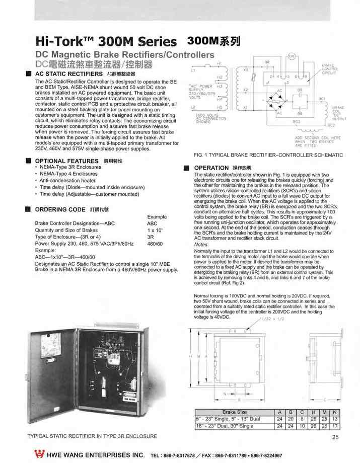
AC STATIC RECTIFIERS
The AC Static/Rec ifier Controller is designed 10 operate the BE and BEM Type,AISE-NEMA shunt wound 50 volt DC shoe brakes installed on AC powered equipment. The basic unit
consists of a multi-tapped power transformer,bridge rectifier,
contactor,statlc control PCB and a protective circuit breaker,all
CON iROl CIRCUI1
mounted on a steel backing plate for pan自I mounting on customer's equipment. The unit is designed with a slalicliming ÀC CONNEC r'ON
circui,l which elìminates relay conlacls. The economizing circuil
reduces power ∞nsumptlon and assures fast brake release
when power is removed. The forcing circullassures faslbrake release when Ihe power is initially applied 10 the brake. AII models are equipped with a multi-tapped p吋mary lransformer for
230V, 460V and 575V slngle-phase power supplies.
- OPTIONAL FEATURES
- NEMA-Type 3R Enclosures
- NEMA-Type 4 Enclosures
- Anli-condensation healer
- Timedelay (Diode→llounted Inside enclosure)
- Timedelay (Adjustable-customer mounted)
ORDERING CODE
Brake Controller Designation-ABC Quantity and Síze of Brakes
Type of Enclosure-(3R or 4)
Power Supply 230, 460, 575 VAC/3Ph/60Hz
Designates an AC Statíc Reclifier to control a single 10" MBE Brake in a NEMA 3R Enclosure from a 460V/60Hz power supply.
OPERATION 操作說明
The static rectlfier/controller shown in Fig. 1 is equipped with two eleclronlccircuits one for releasing Ihe brakes quicl<ly (forcin9) and energizing the brake ∞i1.When the AC vol is applied 10 the
reclifiers (diod) 10 nvert AC inpul10 a full wave DC output forthe olher for maintaining the brakes In the released position.The system utilizes silicon ntrolled rec (SCR's) and sili n
∞ntrol system. the brake relay (BR) is eneized and the two SCR's
∞nduct on allemawe half cycles.Thls results in approximalely 100
volts being applied to the brake coil. The SCR's are triggered by a ee running uni-junction oscillator
which operates for approximateiy one se nd. At the end of the perìod, conduction through
Notes:the SCR's and the brake holding current is maintained by the 24V AC nsformer and rectifler stack cirωit.
Normally the inpullo the ansfoler L1and L2 would be connecled 10 the terrninals of the driving molor and the brake woutd opera!e when power is appiled 10 the molor.If desired the transforrner may be
nnected 10 a fixed AC supply and the brake can be operated by relay (BR) from an ex1emal system. This
is achieved by remof19 Iink5 4 and 5,and Iinks 6 and 7 of the brake
Normal forcing 15 100VDC and normalholdlng 15 20VDC.If requlred. two 50V shunt Wound,brake ∞i15 can be connected in serles and opera!ed from a suibly rated staUc rectlfier ∞nlroller. In thì5 case the
inìtial forcing voltage of Ihe controller Is 200VDC and lhe holding voltage 15 40VDC.
更多商品
2-26.剎車蓋和保護箱BRAKES COVERS/ENCLOSURES
2.300M系列鋼廠級鼓式剎車300M Mill Duty Brakes 下載down load 2-3.說明INTRODUCTION 2-4.訂購資料 ORDERING INFORMATION 2-5.訂購資料 ORDERING INFORMATION 2-6.MBE 型直流磁鐵操作剎車 TYPE MBE DC MAGNET OPERATED BRAKES 2-9.MBT 3相AC油壓致動剎車 TYPE MBT 3-PHASE AC HY-THRUST OPERATED BRAKES 2-10.MBT和MBTE 3相AC油壓致動剎車 TYPE MBT & MBTE 3-PHASE AC HY-THRUST OPERATED BRAKES 2-11.MBT和MBTE尺寸和額定能力 MBT & MBTE DIMENSIONS AND RATING 2-12.BM型.油壓(踏板式)剎車Type BM HYDRAULIC (PEDAL) OPERATED BRAKES 2-13.BM型油壓(踏板式)剎車選用和使用 Type BM Selection and Application 2-14.BEM型DC電磁-油壓鼓式剎車 Type BEM DC MAGNETIC-HYDRAULIC OPERATED SHOE BRAKES 2-15.BEM型DC電磁-油壓鼓式剎車 Type BEM DC MAGNETIC-HYDRAULIC OPERATED SHOE BRAKES 2-16.BEM型DC電磁-油壓鼓式剎車尺寸表和額定能力 The Dimensions and Rating of Type BEM SHOE BRAKES 2-17.BTM和BTME油壓-3相AC油壓致動剎車 MTM & BTME HYDRAULIC-3PHASE AC HY-THRUST OPERATED BRAKES 2-18.BTM和BTME油壓-3相AC油壓致動剎車 MTM & BTME HYDRAULIC-3PHASE AC HY-THRUST OPERATED BRAKES 2-19.BTM和BTME油壓致動剎車尺寸表和額定能力 DIMENSIONS & RATING FOR TYPE MTM & BTME AC HY-THRUST BRAKES 2-20.手動油壓剎車系統-BM , BEM , BTM,BTME 型 MANUAL HYDRAULIC BRAKE SYSTEM-TYPE BM , BEM , BTM & MTME BRAKES 2-21.手動油壓剎車系統 MANUAL HYDRAULIC BRAKE SYSTEM 2-22.剎車鼓-ABW型BRAKE WHEELS-TYPE ABW 2-23.聯軸器BRAKE WHEELS COUPLINGS 2-24.聯軸器尺寸表, DIMENSIONS Of BRAKE WHEELS COUPLINGS 2-25.DC電磁剎車整流器和控制器-BE和BEM型 DC MAGNET BRAKE RECTIFIERS/CONTROLLERS 2-26.剎車蓋和保護箱BRAKES COVERS/ENCLOSURES The standard 300M Sees of AISE-NEMA shoe brakes are sui ble for operalion Indoors. on moist. or dusty applications. When inslIed outdoors or in extremely welor abrasive dust environments. 50me type of brake enclosure is re∞mmended. There are three types of enclosures available to suit a wide variety of installations. Drip Proof- this oonsìsts of a simple paIcover. which extends over the top of the brake wheel and shoes Type 3R- This is a lift off enclosure, which covers the entire brake. The enclosure ìs supplied with a hinged inspection lid and can be provlded with one or two shaft slots Type4一This enclosure is water-tight and dust-tìght and covers the entire brake. The enclosure Is designed with a split gasket f1anged and fitted with one or two shafl seals to suit the installation. For low temperature applications the Type 3R and Type 4 Enclosures may be fitted with a space heate﹒ STANDARD FEATURES 樣準特性 Sheet steel welded construction Primer paint finish Available for all 3 M Series brakes Dimensions avallable on reque.st TYPICAL TYPE 3R BRAKE ENCLOSURE OPTIONAL FEATURES 選用特性 Shafl seals S開闊heaters Thermostats Conduilbox Specìalpaint finish Stainlesssteel
3. 鼓式剎車HI-TORK DRUM BRAKE
3. 鼓式剎車HI-TORK DRUM BRAKE 下載down load 3-2.內容和頁數導引說明CONTENTS AND PAGE REFERENCE GUIDE 3-3.介紹說明INTRODUCTION 3-4.介紹說明INTRODUCTION 3-5.DC磁鐵操作剎車DC MAGNET OPERATED BRAKES 3-6.DC磁鐵操作剎車DC MAGNET OPERATED BRAKES 3-7.3相AC油壓致動器剎車 3 PHASE AC HY-THRUST TM ACTUATOR BRAKES 3-8.3相AC油壓致動器剎車 3 PHASE AC HY-THRUST TM ACTUATOR BRAKES 3-9.3相AC油壓致動器操作/防爆和防火焰剎車 3PHASE AC HY-THRUST TM OPERATED EXPLOSION-PROOF AND FLAME-PROOF BRAKES 3-10.氣動和油壓操作剎車PNEUMATIC AND HYDRAULIC OPERATED BRAKES 3-11.油壓(踏板式)剎車HYDRAULIC (PEDAL) OPERATED BRAKES 3-12.踏板操作油壓系統加到SA , ST和ST/E剎車 PEDAL OPERATED HYDRAULIC OVER-RIDE SYSTEM FOR ADDING TO BRAKE TYPES SA , SA/M , ST AND ST/E BRAKES 3-13.手輪和拉桿致動剎車HANDWHEEL AND LEVER APPLIED BRAKES 3-14.對稱和偏一邊剎車輪轂SYMMETRICAL AND OFFSET HUB BRAKE WHEELS 3-15.齒輪型剎車鼓連軸器GEARED BRAKE WHEEL COUPLINGS 3-16.齒輪型剎車鼓連軸器GEARED BRAKE WHEEL COUPLINGS 3-17.DC磁鐵剎車(SA和SA/M箱型)整流和控制器 DC MAGNET BRAKE (TYPES SA AND SA/M) RECTIFIERS AND CONTROLLERS 3-18.剎車控制箱BRAKE ENCLOSURES
3-2.內容和頁數導引說明CONTENTS AND PAGE REFERENCE GUIDE
3. 鼓式剎車HI-TORK DRUM BRAKE 下載down load 3-2.內容和頁數導引說明CONTENTS AND PAGE REFERENCE GUIDE 3-3.介紹說明INTRODUCTION 3-4.介紹說明INTRODUCTION 3-5.DC磁鐵操作剎車DC MAGNET OPERATED BRAKES 3-6.DC磁鐵操作剎車DC MAGNET OPERATED BRAKES 3-7.3相AC油壓致動器剎車 3 PHASE AC HY-THRUST TM ACTUATOR BRAKES 3-8.3相AC油壓致動器剎車 3 PHASE AC HY-THRUST TM ACTUATOR BRAKES 3-9.3相AC油壓致動器操作/防爆和防火焰剎車 3PHASE AC HY-THRUST TM OPERATED EXPLOSION-PROOF AND FLAME-PROOF BRAKES 3-10.氣動和油壓操作剎車PNEUMATIC AND HYDRAULIC OPERATED BRAKES 3-11.油壓(踏板式)剎車HYDRAULIC (PEDAL) OPERATED BRAKES 3-12.踏板操作油壓系統加到SA , ST和ST/E剎車 PEDAL OPERATED HYDRAULIC OVER-RIDE SYSTEM FOR ADDING TO BRAKE TYPES SA , SA/M , ST AND ST/E BRAKES 3-13.手輪和拉桿致動剎車HANDWHEEL AND LEVER APPLIED BRAKES 3-14.對稱和偏一邊剎車輪轂SYMMETRICAL AND OFFSET HUB BRAKE WHEELS 3-15.齒輪型剎車鼓連軸器GEARED BRAKE WHEEL COUPLINGS 3-16.齒輪型剎車鼓連軸器GEARED BRAKE WHEEL COUPLINGS 3-17.DC磁鐵剎車(SA和SA/M箱型)整流和控制器 DC MAGNET BRAKE (TYPES SA AND SA/M) RECTIFIERS AND CONTROLLERS 3-18.剎車控制箱BRAKE ENCLOSURES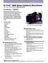
3-3.介紹說明INTRODUCTION
3. 鼓式剎車HI-TORK DRUM BRAKE 下載down load 3-2.內容和頁數導引說明CONTENTS AND PAGE REFERENCE GUIDE 3-3.介紹說明INTRODUCTION 3-4.介紹說明INTRODUCTION 3-5.DC磁鐵操作剎車DC MAGNET OPERATED BRAKES 3-6.DC磁鐵操作剎車DC MAGNET OPERATED BRAKES 3-7.3相AC油壓致動器剎車 3 PHASE AC HY-THRUST TM ACTUATOR BRAKES 3-8.3相AC油壓致動器剎車 3 PHASE AC HY-THRUST TM ACTUATOR BRAKES 3-9.3相AC油壓致動器操作/防爆和防火焰剎車 3PHASE AC HY-THRUST TM OPERATED EXPLOSION-PROOF AND FLAME-PROOF BRAKES 3-10.氣動和油壓操作剎車PNEUMATIC AND HYDRAULIC OPERATED BRAKES 3-11.油壓(踏板式)剎車HYDRAULIC (PEDAL) OPERATED BRAKES 3-12.踏板操作油壓系統加到SA , ST和ST/E剎車 PEDAL OPERATED HYDRAULIC OVER-RIDE SYSTEM FOR ADDING TO BRAKE TYPES SA , SA/M , ST AND ST/E BRAKES 3-13.手輪和拉桿致動剎車HANDWHEEL AND LEVER APPLIED BRAKES 3-14.對稱和偏一邊剎車輪轂SYMMETRICAL AND OFFSET HUB BRAKE WHEELS 3-15.齒輪型剎車鼓連軸器GEARED BRAKE WHEEL COUPLINGS 3-16.齒輪型剎車鼓連軸器GEARED BRAKE WHEEL COUPLINGS 3-17.DC磁鐵剎車(SA和SA/M箱型)整流和控制器 DC MAGNET BRAKE (TYPES SA AND SA/M) RECTIFIERS AND CONTROLLERS 3-18.剎車控制箱BRAKE ENCLOSURES Magnetek's heavy-duty,cost-effective Mondel Industrial Duty Shoe Brakes are designed for a wide va巾ty of industrial and mining applications and environments. Minimal moving parts provides an extremely reliable range of brakes that are easy to install adjust and maintain. The 200S Brake Series has ampact size with low shaft height making it easy to retrofit into existing installations where space is tight Applications include:ConveyorsOverhead cranes Hoists Bridges Movable Bridges Fans Winches Tumtables Overhead Doors Lock Gates Strip Processing EquipmentOre BridgesShip LoadersOther types of machinery requirìng reliable stopping and holdingMachine Tools STANDARDFEATURES 標準特性 Environmentally safe molded non-asbestos brake linings provide a constant coefficíent of friction over the normal operating temperature range.Standardlinings are bonded to the brake shoes to provide a maximum amount of shoe wear. Brake shoes are pivoted; automatic positioners prevent the shoes from dragging on the brake wheel. Serîes wound coils for all currents.Shunt wound ∞ils for all popular voltages. AC operators are C.S.A. certified for all popular voltages and frequencies. Top hinged armatures on DC magn的 keep air gap free from dirt and debris.Hardwareís non-corrosíve. BRAKE WHEELS 剎車鼓 Standard wheels are st in a ductile iron allo Wheel material endures high temperatures and is resistant to scouring . Wheels available to meet customers' specifications ; from fully machined and balanced to semi-finished rough bored. BRAKE WHEEL COUPLNGS 剎車鼓連軸器Brake wheel coupngs avaìlable for all sizes of 200S Series brake wheels. BRAKE RECTIFIERS AND BRAKE CONTROLLERS 剎車整流和控制器 Rectifiers allow a DC magnet brake to be utili zed with an AC power supply. Hoist brake rectifiers i nclude a forci ng/hold lng circuit to minimize set and release times. Standard conlroller designed to operate BE Series brake with shunt wound 50 VDC coil. Standard controller supplied ín a NEMA 3R Enclosure.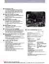
3-4.介紹說明INTRODUCTION-02
3. 鼓式剎車HI-TORK DRUM BRAKE 下載down load 3-2.內容和頁數導引說明CONTENTS AND PAGE REFERENCE GUIDE 3-3.介紹說明INTRODUCTION 3-4.介紹說明INTRODUCTION 3-5.DC磁鐵操作剎車DC MAGNET OPERATED BRAKES 3-6.DC磁鐵操作剎車DC MAGNET OPERATED BRAKES 3-7.3相AC油壓致動器剎車 3 PHASE AC HY-THRUST TM ACTUATOR BRAKES 3-8.3相AC油壓致動器剎車 3 PHASE AC HY-THRUST TM ACTUATOR BRAKES 3-9.3相AC油壓致動器操作/防爆和防火焰剎車 3PHASE AC HY-THRUST TM OPERATED EXPLOSION-PROOF AND FLAME-PROOF BRAKES 3-10.氣動和油壓操作剎車PNEUMATIC AND HYDRAULIC OPERATED BRAKES 3-11.油壓(踏板式)剎車HYDRAULIC (PEDAL) OPERATED BRAKES 3-12.踏板操作油壓系統加到SA , ST和ST/E剎車 PEDAL OPERATED HYDRAULIC OVER-RIDE SYSTEM FOR ADDING TO BRAKE TYPES SA , SA/M , ST AND ST/E BRAKES 3-13.手輪和拉桿致動剎車HANDWHEEL AND LEVER APPLIED BRAKES 3-14.對稱和偏一邊剎車輪轂SYMMETRICAL AND OFFSET HUB BRAKE WHEELS 3-15.齒輪型剎車鼓連軸器GEARED BRAKE WHEEL COUPLINGS 3-16.齒輪型剎車鼓連軸器GEARED BRAKE WHEEL COUPLINGS 3-17.DC磁鐵剎車(SA和SA/M箱型)整流和控制器 DC MAGNET BRAKE (TYPES SA AND SA/M) RECTIFIERS AND CONTROLLERS 3-18.剎車控制箱BRAKE ENCLOSURES ENVIRONMENT 環境 The standard 200S Series 8rakes has been designed to function in moderately dusty and moist locations. The AC and DC actuators are sealed,encapsulated or gasketed. 8rake components and associated hardware are painted, BRAKE ENCLOSURES 剎車控制箱plated or corrosion resistant. Custom enclosures are designed to protect the brake fr its application environment. Available in NEMA 3R and NEMA 4 design ∞nfigurations. SPACE HEATERS 空間加熱器 In low temperature and/or damp10 tions,where condensation may be a problem,space heaters n be provided for mounting insid e brake enclosures.Hy-Thrust actuators are available with optional bui lt in heaters. BRAKETRONIC TM 電子剎車 AC/DC variable frequency torque control of thruster operated shoe or disc brake. HAZARDOUS LOCATIONS 危險場所 Hy-Thrust actuators are widely used in explosion-proof and f1ame-proof areas on Drum,8and, and Disc brakes for con veyors,hoists,cranes,and many other applications in the mining, petro-chemical and material handling industries INSTALLATION,MAINTENANCE AND SPARE PARTS安裝維修和備品 Specífic ínstallation,operation,and maintenance information and spare parts lists are shipped with each brake. Additional ∞pies are available on request or downloed from Mechanical and magnetíc proximity interlockllimit switches thewww.mondelenaineerina m web site. OPTIONAL FEATURES 選用 Extra wide shoes 80lted or riveted linings 8rake shoe thermostats to monitor brake wheel temperatures 8rake lining replacement waminglìnterlock system Hydraulic over-ride/parking/emergency stopping Stainless steel pivotpins Special pivot pins,fitted with lubricators,for harsh environment applications Latching manual release lever Mechanical and magnetíc proximity interlockllimit switches Tropical and corrosion protection Vertical mounting on certain models Brake Size and Type Torque HP speed of shaft on which brake is mounted (RPM) 8rake application Electrical Supply Shunt/Series Wound Coil Rating Motor data fo‘r S Series Wound Coil Duty Cycle Ambíent Temperature Optional Features For replacement brakes,provide the original brake nameplate information. Refer to Selection and Application Data section in our Product 8inder. ACCESSORIES 8rake Wheels/Couplings,RectifieIConollers, Covers, and 8raketronic. Order as required.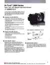
3-5.DC磁鐵操作剎車DC MAGNET OPERATED BRAKES
3. 鼓式剎車HI-TORK DRUM BRAKE 下載down load 3-2.內容和頁數導引說明CONTENTS AND PAGE REFERENCE GUIDE 3-3.介紹說明INTRODUCTION 3-4.介紹說明INTRODUCTION 3-5.DC磁鐵操作剎車DC MAGNET OPERATED BRAKES 3-6.DC磁鐵操作剎車DC MAGNET OPERATED BRAKES 3-7.3相AC油壓致動器剎車 3 PHASE AC HY-THRUST TM ACTUATOR BRAKES 3-8.3相AC油壓致動器剎車 3 PHASE AC HY-THRUST TM ACTUATOR BRAKES 3-9.3相AC油壓致動器操作/防爆和防火焰剎車 3PHASE AC HY-THRUST TM OPERATED EXPLOSION-PROOF AND FLAME-PROOF BRAKES 3-10.氣動和油壓操作剎車PNEUMATIC AND HYDRAULIC OPERATED BRAKES 3-11.油壓(踏板式)剎車HYDRAULIC (PEDAL) OPERATED BRAKES 3-12.踏板操作油壓系統加到SA , ST和ST/E剎車 PEDAL OPERATED HYDRAULIC OVER-RIDE SYSTEM FOR ADDING TO BRAKE TYPES SA , SA/M , ST AND ST/E BRAKES 3-13.手輪和拉桿致動剎車HANDWHEEL AND LEVER APPLIED BRAKES 3-14.對稱和偏一邊剎車輪轂SYMMETRICAL AND OFFSET HUB BRAKE WHEELS 3-15.齒輪型剎車鼓連軸器GEARED BRAKE WHEEL COUPLINGS 3-16.齒輪型剎車鼓連軸器GEARED BRAKE WHEEL COUPLINGS 3-17.DC磁鐵剎車(SA和SA/M箱型)整流和控制器 DC MAGNET BRAKE (TYPES SA AND SA/M) RECTIFIERS AND CONTROLLERS 3-18.剎車控制箱BRAKE ENCLOSURESwill provide a long service life with a minimum amount of mainThe "SA" type brake is a sp吋ng applied,electrilJy released DC shoe brake,utilizing a short e magnet designed to pr' U臼 a quìck acting brake with a low armature impact. These brakes tenance and downtìme. STANDARDFEATURES 標準特性 Compact design,requires mìnimum installation spa. Braking torque may be adjusted to 50% of the maximum torque. Double torque sprlngs一in the event one fails the other wilJ provlde partìal torque. Easy adjustments are provided for sp叫ng pressure,magnet air gap and shoe cJearance. Top hlnged magnet prevents dirt and debris from building up between the magnet case and the armature. Class“F"Insulation A weather-proof (Type 3R) terminal box is provided on all shunt brakes. The air gap shield is fitted to prevent dirt from faJling between the armature and the actuator. OPTIONAL FrURES選用特性 Hydraulic over-ride/parking/emergency stopping Built-inRectifier---an en臼psulated diode bride 臼 n be mounted inside the terminal box Shunt discharge unit Tímedelay (for up to 1.0 )Manual latching brake release level SHUNT BRAKES 並聯剎車 Standard shunt brakes are continuous (8 Hr.) rated and designed for Class“B" temperature rise at a maximum 40 0C ambient. At fulJ torque,maximum air-gap and normal operating temperatures,the brakes are designed to release at 80% of fulJ line voltage. Shunt wound brakes be supplied for 12V to 550V DC operation. The“pick-up﹒times of shunt operated brakes be improved by implementing or the“ resistance" forcing methods. With the voltage method,a standard il is forced" by the application of 2 to 3 times normal volts for approximately a 1 /2 second (Ref. Fig. 1). Using the resistance method,a partial voltage coil is used in sees with a suible resistance which is ntrolJed by a heavy duty ntactor. SERIES BRAKES 串聯剎車 Series brakes are available wìth coils designed for 1/2 hour and 1-hour duty to correspond with the relevant motor horse power ratings and currents. The brakes wilJ release at 40% fulJ-load motor current and remain released down to 10% full load motor current.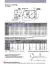
3-6.DC磁鐵操作剎車DC MAGNET OPERATED BRAKES-02
3. 鼓式剎車HI-TORK DRUM BRAKE 下載down load 3-2.內容和頁數導引說明CONTENTS AND PAGE REFERENCE GUIDE 3-3.介紹說明INTRODUCTION 3-4.介紹說明INTRODUCTION 3-5.DC磁鐵操作剎車DC MAGNET OPERATED BRAKES 3-6.DC磁鐵操作剎車DC MAGNET OPERATED BRAKES 3-7.3相AC油壓致動器剎車 3 PHASE AC HY-THRUST TM ACTUATOR BRAKES 3-8.3相AC油壓致動器剎車 3 PHASE AC HY-THRUST TM ACTUATOR BRAKES 3-9.3相AC油壓致動器操作/防爆和防火焰剎車 3PHASE AC HY-THRUST TM OPERATED EXPLOSION-PROOF AND FLAME-PROOF BRAKES 3-10.氣動和油壓操作剎車PNEUMATIC AND HYDRAULIC OPERATED BRAKES 3-11.油壓(踏板式)剎車HYDRAULIC (PEDAL) OPERATED BRAKES 3-12.踏板操作油壓系統加到SA , ST和ST/E剎車 PEDAL OPERATED HYDRAULIC OVER-RIDE SYSTEM FOR ADDING TO BRAKE TYPES SA , SA/M , ST AND ST/E BRAKES 3-13.手輪和拉桿致動剎車HANDWHEEL AND LEVER APPLIED BRAKES 3-14.對稱和偏一邊剎車輪轂SYMMETRICAL AND OFFSET HUB BRAKE WHEELS 3-15.齒輪型剎車鼓連軸器GEARED BRAKE WHEEL COUPLINGS 3-16.齒輪型剎車鼓連軸器GEARED BRAKE WHEEL COUPLINGS 3-17.DC磁鐵剎車(SA和SA/M箱型)整流和控制器 DC MAGNET BRAKE (TYPES SA AND SA/M) RECTIFIERS AND CONTROLLERS 3-18.剎車控制箱BRAKE ENCLOSURES -Hydraulic override not available. NOTES: 1- CUSTOM BRAKE SIZES AVAILABLE,CONSULT FACTORY For selection and application da refer 10 Application/Engineering Bulletin. TYPICAL TIME-CURRENT CURVES FOR SHUNT BRAKES WITH AND WITHOUT FORCING. ﹒This method of control is typìcally used to improve the response times of brakes on crane hoìst applications.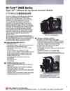
3-7.3相AC油壓致動器剎車3 PHASE AC HY-THRUST TM ACTUATOR BRAKES
3. 鼓式剎車HI-TORK DRUM BRAKE 下載down load 3-2.內容和頁數導引說明CONTENTS AND PAGE REFERENCE GUIDE 3-3.介紹說明INTRODUCTION 3-4.介紹說明INTRODUCTION 3-5.DC磁鐵操作剎車DC MAGNET OPERATED BRAKES 3-6.DC磁鐵操作剎車DC MAGNET OPERATED BRAKES 3-7.3相AC油壓致動器剎車 3 PHASE AC HY-THRUST TM ACTUATOR BRAKES 3-8.3相AC油壓致動器剎車 3 PHASE AC HY-THRUST TM ACTUATOR BRAKES 3-9.3相AC油壓致動器操作/防爆和防火焰剎車 3PHASE AC HY-THRUST TM OPERATED EXPLOSION-PROOF AND FLAME-PROOF BRAKES 3-10.氣動和油壓操作剎車PNEUMATIC AND HYDRAULIC OPERATED BRAKES 3-11.油壓(踏板式)剎車HYDRAULIC (PEDAL) OPERATED BRAKES 3-12.踏板操作油壓系統加到SA , ST和ST/E剎車 PEDAL OPERATED HYDRAULIC OVER-RIDE SYSTEM FOR ADDING TO BRAKE TYPES SA , SA/M , ST AND ST/E BRAKES 3-13.手輪和拉桿致動剎車HANDWHEEL AND LEVER APPLIED BRAKES 3-14.對稱和偏一邊剎車輪轂SYMMETRICAL AND OFFSET HUB BRAKE WHEELS 3-15.齒輪型剎車鼓連軸器GEARED BRAKE WHEEL COUPLINGS 3-16.齒輪型剎車鼓連軸器GEARED BRAKE WHEEL COUPLINGS 3-17.DC磁鐵剎車(SA和SA/M箱型)整流和控制器 DC MAGNET BRAKE (TYPES SA AND SA/M) RECTIFIERS AND CONTROLLERS 3-18.剎車控制箱BRAKE ENCLOSURES The ST (and ST/E) type,3-phase AC shoe brakes are spring applied-electrically released by a completely sealed, continuously rated,Hy-Thrust actuator. These brakes are designed with a minimum number of parts 1.0 provide a long service life with reduced maintenance and downtime This versatìle brake can be applied to a wide range of applications and environmental conditions,where smooth, responsive stopping and holding is required. The cushioned brake action produces signmcantly less mechanical oscillations as compared to the DC Armature or the AC Solenoid type brakes. The latter are notoriously expensive to maintain in terms of spare parts and downtime.The inherent cushioning effect makes the brake ideal for high duty cycles or jogging applications,virtually eliminating mechanical shock loading which can lead to increased component wear and or component failures. Since the growth in popularlty of AC controlled cranes,this brake has rapidJy become the standard for all crane motions. It has the same high reliability that is normally associated with the DC Armature brakes,but does not require an expensive transformer/rectifier controller to supply the DC power. STANDARDFEATURES 標準特性 Fast response times High switching frequency-1200 to 2000 operations per hour Long service life-20mlllion switching cycles Working f1uidoperating range -吟。F ( 。C) through 122 F (50 C) Built-in compression sp討ng (Standard "ST" Type) Available for 230VAC,460VAC,575VAC/3 Ph/60Hz as standard. Environmentally safe molded non-asbestos brake IInings provide a constant coefficient of friction over the normal operating temperature range.Convenient adjustments for torque,lining wear and shoe clearance. Manual release lever Floor mounting OPTIONAL FEATURES 選用特性 Stepless,extemally adjustable time detays for Setting ("S",) Releasing (“H") Special f1uidsoperating in extreme ambient temperatures Extemaltorque spgs(“ST/E"Type) ﹒Tropiiz,explosion-proof and f1ame-proof units available Corrosion protection Braketronic stepless remote braking available (nsult factory) • Hydraulic pedal operated manual over-ride systems BRAKING TORQUES 剎車扭力 The standard Type “STnternal torque spring) Torque spring compression rating is fixed within the thruster. Prsettoues ng provided by pull rod pivot pin locations (3). Torque may be reduoed to 60% of maximum rating. The optionalType “ST/E"(temaltoue spng) Provides steple torque adjustrnent﹒ Torque adjustment made by rotating the nut atop the spring tube assembly.Torque may be reduced to 40% of maximum rating. Theactualsetting can be read on the calibrated toue inditor (C.T.I.) 10ted in the side of the spring tube assembly.