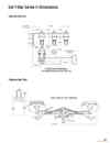
1-3-1.SAF-T-BAR T型電軌(T SERIES CONDUCTOR)
 點擊圖片放大
商品名稱:
1-3-1.SAF-T-BAR T型電軌(T SERIES CONDUCTOR)
詳細介紹:
1.C&W電軌系統(SAF-T-BAR)新目錄
1-1.SAF-T-BAR C型電軌(C SERIES CONDUCTOR) 下載down load
1-2.SAF-T-BAR H型電軌(H SERIES CONDUCTOR) 下載down load
1-3.SAF-T-BAR T型電軌(T SERIES CONDUCTOR) 下載down load
1-4.INSUL-8 8字型電軌(INSUL-8 CONDUCTOR) 下載down load
1-5.INSUL-8側向8型電軌(INSUL-8 SIDE CONTACT CONDUCTOR BAR) 下載down load
1-6.CLUSTER電軌CLUSTER BAR 下載down load
更多商品
1-2-13.SAF-T-BAR H型電軌(H SERIES CONDUCTOR)
1.C&W電軌系統(SAF-T-BAR)新目錄 1-1.SAF-T-BAR C型電軌(C SERIES CONDUCTOR) 下載down load 1-2.SAF-T-BAR H型電軌(H SERIES CONDUCTOR) 下載down load 1-3.SAF-T-BAR T型電軌(T SERIES CONDUCTOR) 下載down load 1-4.INSUL-8 8字型電軌(INSUL-8 CONDUCTOR) 下載down load 1-5.INSUL-8側向8型電軌(INSUL-8 SIDE CONTACT CONDUCTOR BAR) 下載down load 1-6.CLUSTER電軌CLUSTER BAR 下載down load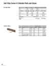
1-2-12.SAF-T-BAR H型電軌(H SERIES CONDUCTOR)
1.C&W電軌系統(SAF-T-BAR)新目錄 1-1.SAF-T-BAR C型電軌(C SERIES CONDUCTOR) 下載down load 1-2.SAF-T-BAR H型電軌(H SERIES CONDUCTOR) 下載down load 1-3.SAF-T-BAR T型電軌(T SERIES CONDUCTOR) 下載down load 1-4.INSUL-8 8字型電軌(INSUL-8 CONDUCTOR) 下載down load 1-5.INSUL-8側向8型電軌(INSUL-8 SIDE CONTACT CONDUCTOR BAR) 下載down load 1-6.CLUSTER電軌CLUSTER BAR 下載down load Type L Series D Series Heat Sink L Series Heat Sink D Series Body 302B 50-901 302B Contact Shoe 300SHP (6") 400SHP (8") 300SHP (6") 400SHP (8") 400SHPHS (x2) 400SHPHS (x2) Spring 300Z 300Z 300Z 300Z Arm 300LP 50-902 300LP 50-902 Spool 1000Q 1000Q 50-906 50-906 Welding cable WR002RD1600 Heat sink as- sembly - - 400YHP-Head 400YHP-Head Capacity (amps) Qty Description Shoe Size Continuous Intermittent Part No. 1 Single 5/8" x 6" 200 300 300SHP 2 Dual 5/8" x 6" 400 600 300SHP 1 Single 5/8 x 8" 300 450 400SHP 2 Dual 5/8 x 8" 600 900 400SHP 1 Single, Heat Sink Design 5/8 x 8" 400 500 400SHPHS 2 Dual, Heat Sink Design 5/8 x 8" 800 1000 400SHPHS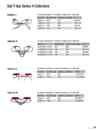
1-2-11.SAF-T-BAR H型電軌(H SERIES CONDUCTOR)
1.C&W電軌系統(SAF-T-BAR)新目錄 1-1.SAF-T-BAR C型電軌(C SERIES CONDUCTOR) 下載down load 1-2.SAF-T-BAR H型電軌(H SERIES CONDUCTOR) 下載down load 1-3.SAF-T-BAR T型電軌(T SERIES CONDUCTOR) 下載down load 1-4.INSUL-8 8字型電軌(INSUL-8 CONDUCTOR) 下載down load 1-5.INSUL-8側向8型電軌(INSUL-8 SIDE CONTACT CONDUCTOR BAR) 下載down load 1-6.CLUSTER電軌CLUSTER BAR 下載down load For collector movement of 2" in direction of contact and ± 1" lateral drift. Description Intermittent Only Continuous or Intermittent Part No. Single arm 300A 200A HA300LS Tandem arm 600A 400A HA600LLS Single arm 450A 300A HA400LS Tandem arm 900A 600A HA800LLS Description Intermittent Only Continuous or Intermittent Part No. Dual Parallel Arm, Single 300A 200A HA300DS Dual Parallel Arm, Tandem 600A 200A HA600DDS Dual Parallel Arm, Single 450A 300A HA400DS Dual Parallel Arm, Tandem 900A 600A HA800DDS For collector movement of 2" in direction of contact and ± 1" lateral drift. Description Intermittent Only Continuous or Intermittent Part No. Single arm 500A 400A HA400LSHS Tandem arm 1000A 800A HA800LLSHS For collector movement of 3" in direction of contact and ± 3" lateral drift Description Intermittent Only Continuous or Intermittent Part No. Single arm 500A 400A HA400DSHS Tandem arm 1000A 800A HA800DDSHS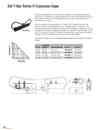
1-2-10.SAF-T-BAR H型電軌(H SERIES CONDUCTOR)
1.C&W電軌系統(SAF-T-BAR)新目錄 1-1.SAF-T-BAR C型電軌(C SERIES CONDUCTOR) 下載down load 1-2.SAF-T-BAR H型電軌(H SERIES CONDUCTOR) 下載down load 1-3.SAF-T-BAR T型電軌(T SERIES CONDUCTOR) 下載down load 1-4.INSUL-8 8字型電軌(INSUL-8 CONDUCTOR) 下載down load 1-5.INSUL-8側向8型電軌(INSUL-8 SIDE CONTACT CONDUCTOR BAR) 下載down load 1-6.CLUSTER電軌CLUSTER BAR 下載down load Expansion Gap assemblies are pre-assembled and ready to be installed between two adjacent sections of rail to compensate for thermal expansion of the rail due to environmental changes and power-generated heat. Each end of the expansion section is attached to its mating rail with a powerfeed type of rail splice. Aluminum conductors will expand one inch in 70 feet per 100o F temperature variation. The Expansion Gap will handle expansions of up to 8". The Expansion Gap assembly is 12" long "closed" and 20" long expanded (with the maximum gap of 8".) The gap is normally set at 4" in an average 600 F environment. An Expansion Gap assembly is required for every 500 feet (or fraction thereof) in system length to handle a 100 degree F maximum temperature variation. A proportional decrease in the 500 foot interval is required for greater temperature variations. Center point of all conductor runs using expansion gaps requires an anchor clamp kit to locate rail settings. For Bar Powerfeeds included Jumpers included Part No. Wt lb (kg) HC500 HA500F # 3/0 x 40" HA500XG-8" 13.0 (5.90) HC750 HA750F Two # 3/0 x 50" HA750XG-8" 13.0 (5.90) HC1000 HA1000F Two # 3/0 x 50" HA1000XG-8" 15.0 (6.80) HC1500 HA1500F Two 350 MC x 50" HA1500XG-8" 20.0 (9.07)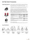
1-2-9.SAF-T-BAR H型電軌(H SERIES CONDUCTOR)
1.C&W電軌系統(SAF-T-BAR)新目錄 1-1.SAF-T-BAR C型電軌(C SERIES CONDUCTOR) 下載down load 1-2.SAF-T-BAR H型電軌(H SERIES CONDUCTOR) 下載down load 1-3.SAF-T-BAR T型電軌(T SERIES CONDUCTOR) 下載down load 1-4.INSUL-8 8字型電軌(INSUL-8 CONDUCTOR) 下載down load 1-5.INSUL-8側向8型電軌(INSUL-8 SIDE CONTACT CONDUCTOR BAR) 下載down load 1-6.CLUSTER電軌CLUSTER BAR 下載down load Hanger clamp bracket should be attached to the runway beam by welding or bolting. Conductors should be spaced 5" (127 mm) inches apart, however, a minimum of 3.5" (89 mm) is acceptable. Hanger clamp brackets require 9/16" (14.3 mm) holes for 1/2" hanger clamp bolts. To properly support the conductor and to keep standard rail overhang to 24" (610 mm), space the first two brackets on 6' (1.83 m) centers and all other brackets on 10' (3.05 m) centers. The "Anchor" is a non-sliding version of the hanger which provides a solid fixing point on the conductor bar. Anchor clamp kit consists of an insulated keeper straddling each side of the standard hanger. The usual hanger bolt is replaced by a cup-point set screw that is tightened against the keeper plate at the desired anchor location. On HA1000H hangers, the set screw becomes the mounting bolt. ON HA1000K hangers, the set screw is threaded into the base of the insulator spool. HA1000PA anchors come with a drilled hole in the vertical stiffener. At the instal- lation site, a hole is drilled through the conductor bar to accommodate a threaded rod. Threaded rod is captured by acorn nuts on both sides of the clamp. Hanger Clamp Type 2 Usage Part No. 1 Wt lb (kg) Hanger, coated steel Normal atmospheres HA1000H 0.5 (0.23) Hanger, coated steel with insulator spool Wet atmospheres HA1000K 1.0 (0.45) Hanger, Plastic In lieu of: HA1000H or HA1000K HA1000P 0.5 (0.23) Anchor, coated steel with anchor clamp kit Normal atmospheres HA1000HA 0.6 (0.27) Anchor, coated steel with insulator spool and anchor clamp kit Wet atmospheres HA1000KA 1.1 (0.50) Anchor, plastic with anchor clamp kit HA1000PA 0.6 (0.27) Suffix "A" indicates anchor options All H Series components are available with stainless steel hardware, designated by the suffix "SS"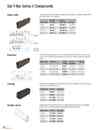
1-2-8.SAF-T-BAR H型電軌(H SERIES CONDUCTOR)
1.C&W電軌系統(SAF-T-BAR)新目錄 1-1.SAF-T-BAR C型電軌(C SERIES CONDUCTOR) 下載down load 1-2.SAF-T-BAR H型電軌(H SERIES CONDUCTOR) 下載down load 1-3.SAF-T-BAR T型電軌(T SERIES CONDUCTOR) 下載down load 1-4.INSUL-8 8字型電軌(INSUL-8 CONDUCTOR) 下載down load 1-5.INSUL-8側向8型電軌(INSUL-8 SIDE CONTACT CONDUCTOR BAR) 下載down load 1-6.CLUSTER電軌CLUSTER BAR 下載down loadThe bolted Splice Joint assembly is comprised of two stacked spring plates located inside the hollow portion of the conductor. Used on Bar: Part No. Std Heat Part No. Med Heat Wt (kg) HC500 HA500J HA500HHJ 1.0 (0.45) HC750 HA750J HA750HHJ 1.5 (0.48) HC1000 HA1000J HA1000HHJ 2.0 (0.91) HC1500 HA1500J HA1500HHJ 3.0 (1.36) The Powerfeed supplies power to the bar and is inserted in place of the bar splice joint. Or it can be mounted at any point along the conductor by cutting the bar and insulating cover. Used on Bar: Terminals Part No. Std Heat Part No. Med Heat Wt lb (kg) HC500 Two 350 MCM HA500F HA500HHF 3.0 (1.36) HC750 Two 350 MCM HA750F HA750HHF 3.0 (1.36) HC1000 Two 350 MCM HA1000F HA1000HHF 3.0 (1.36) HC1500 Three 350 MCM-2 HA1500F HA1500HHF 6.0 (2.72) Used on Bar: Part No. Wt lb (kg) HC500 HA1000IS 2.0 (0.91) HC750 HA1000IS 2.0 (0.91) HC1000 HA1000IS 2.0 (0.91) HC1500 HA1000IS 2.0 (0.91) Isolation joints are required for circuit segmentation and are comprised of an insulating angle with attachment hardware to secure and space the adjacent rails.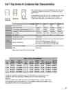
1-2-7.SAF-T-BAR H型電軌(H SERIES CONDUCTOR)
1.C&W電軌系統(SAF-T-BAR)新目錄 1-1.SAF-T-BAR C型電軌(C SERIES CONDUCTOR) 下載down load 1-2.SAF-T-BAR H型電軌(H SERIES CONDUCTOR) 下載down load 1-3.SAF-T-BAR T型電軌(T SERIES CONDUCTOR) 下載down load 1-4.INSUL-8 8字型電軌(INSUL-8 CONDUCTOR) 下載down load 1-5.INSUL-8側向8型電軌(INSUL-8 SIDE CONTACT CONDUCTOR BAR) 下載down load 1-6.CLUSTER電軌CLUSTER BAR 下載down loadSeries H Conductor Bars are constructed of extruded aluminum with a stainless steel “U” shaped contact surface which guides collector shoe movement and minimizes collector shoe wear.Bars are provided in four sizes: 500, 750, 1000, or 1500 Amp, each with "Standard Heat" rigid PVC insulation, "Medium Heat" Lexan, or "High Heat" fiberglass insulations are available by request. The standard rail length is 20 feet (6.10 m). Bar Type: HC500 HC750 HC1000 HC1500 Specifications Nominal Current (amps) 1 500 750 1000 1500 DC Resistance (ohms/ft) 0.0000194 0.0000194 0.0000155 0.0000067 AC Impedance (ohms/ft at 60Hz) measured at 3.5" c/c 0.0000301 0.0000301 0.0000279 0.0000389 AC Impedance (ohms/ft at 60Hz) measured at 5.0" c/c 0.0000363 0.0000363 0.0000355 0.0000385 Wt lb/ft (kg/m) 1.390 (0.1922) 1.390 (0.1922) 1.616 (0.2234) 3.141(0.4328) Max. Voltage (V) 600 600 600 600 Common Characteristics Nominal Support Spacing (ft) 10 foot (3.05 m) Standard Rail Length (ft) 20 ft (6.10 m) Maximum Rail Temperature 160O F (71.1O C) at 260 PSI (Standard Heat Cover) 260O F (126.7O C) at 260 PSI (Medium Heat Lexan Cover) 360O F (182.2O C) at 260 PSI (High Heat Fiberglass Cover) Conductor Mounting Orientation Can be installed vertically or horizontally Curves Consult Factory 1 Nominal current is based on 30°C and is for 100% duty. Basic Series H Part Numbers 6 Bar Type Phase Conductor Std Heat 2 Phase Conductor Med WT Heat 3 lb (kg) Joint Kit Std Heat 4 Joint Kit Med Heat Lexan 4 Power Feed Std Heat 4 Expansion Gap Assemblies 5 Power Feed Med Heat Lexan 4 HC500 HC500X20 HC500HHX20 24.0 (10.89) HA500J HA500HHJ HA500F HA500XG-8* HA500HHF HC750 HC750X20 HC750HHX20 24.0 (10.89) HA750J HA750HHJ HA750F HA750XG-8* HA750HHF HC1000 HC1000X20 HC1000HHX20 30.0 (13.61) HA1000J HA1000HHJ HA1000F HA1000XG-8* HA1000HHF HC1500 HC1500X20 HC1500HHX20 60.0 (27.22) HA1500J HA1500HHJ HA1500F HA1500XG-8* HA1500HHF 2 Complete with "standard heat" cover (orange rigid PVC, 160°F heat distortion point, 260 psi, self extinguishing) 3 Complete with "medium heat" cover (red Lexan, 260°F heat distortion point, 260 psi, self extinguishing) 4 See Pg. 72 5 Powerfeeds and Expansion kits: medium heat Lexan and high heat fiberglass versions are available - Contact Factory 6 End caps available for standard heat applications only - Part Nos.: HA500N, HA750N, HA1000N, HA1500N - See pg. 72 (Also available with white PVC (UV) cover for standard heat systems)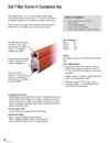
1-2-6.SAF-T-BAR H型電軌(H SERIES CONDUCTOR)
1.C&W電軌系統(SAF-T-BAR)新目錄 1-1.SAF-T-BAR C型電軌(C SERIES CONDUCTOR) 下載down load 1-2.SAF-T-BAR H型電軌(H SERIES CONDUCTOR) 下載down load 1-3.SAF-T-BAR T型電軌(T SERIES CONDUCTOR) 下載down load 1-4.INSUL-8 8字型電軌(INSUL-8 CONDUCTOR) 下載down load 1-5.INSUL-8側向8型電軌(INSUL-8 SIDE CONTACT CONDUCTOR BAR) 下載down load 1-6.CLUSTER電軌CLUSTER BAR 下載down load The advanced "Series H" Saf-T-Bar system features integral insulated conductors to provide years of safe, economical, and trouble-free service. It is designed for compact, low-cost installation, and minimum maintenance. Series H conductors are supplied in 20 foot lengths with factory installed insulating covers. Joint fittings and covers are ordered separately. Skin-tight insulation runs cooler, will not deform under clamp pressure. Standard insulation is 160o F (71o C). Alternative insulations are available Metal guideways assure positive tracking of collector shoe with or without insulating cover Flat contact surface for maximum conductor wear; the stainless steel channel insert provides resistance to corrosion and electrical pitting. Atmospheric specifications In wet atmospheres, the system should be mounted on insulated hangers with the conductor in the downturn position. In dirty and dusty atmospheres, mount the conductor in the downturn position. If the atmosphere is likely to cause electrical over-surface tracking, choose hanger clamps with spool insulators rather than the standard coated hanger clamp. Insulating hanger option A plastic slide hanger is available as an alternative design. Insulating cover options Prefix A Standard rigid vinyl for cranes and hoists Suffix H Medium heat plastic to 260oF for cranes and hoists Suffix Fl High heat fiberglass to 375oF for cranes and hoists Series H is ideal for: Heavy duty cranes and monorails Wet locations Port authority equipment Dusty and dirty environments Environments conducive to electrical tracking Current Capacities HC500 500 HC750 750 HC1000 1000 HC1500 1500 Material All capacities: Aluminum with 304 Stainless Steel Contact Strip Other available features Contact shoe with flat surface of sintered copper and graphite, self-lubricating to effective draw current to the collector. Heat sink collector heads available for high current draw. Compact mounting of conductor in vertical or horizontal position without special parts or fittings. • Collectors are available in either single or dual arm construction. Single (L, LL), and pantograph dual-arm constructions (D, DD) are available.