2-10.MBT和MBTE 3相AC油壓致動剎車TYPE MBT & MBTE 3-PHASE AC HY-THRUST OPERATED BRAKES
 點擊圖片放大
2-10.MBT和MBTE 3相AC油壓致動剎車TYPE MBT & MBTE 3-PHASE AC HY-THRUST OPERATED BRAKES
2.300M系列鋼廠級鼓式剎車300M Mill Duty Brakes 下載down load
2-3.說明INTRODUCTION
2-4.訂購資料 ORDERING INFORMATION
2-5.訂購資料 ORDERING INFORMATION
2-6.MBE 型直流磁鐵操作剎車
TYPE MBE DC MAGNET OPERATED BRAKES
2-9.MBT 3相AC油壓致動剎車
TYPE MBT 3-PHASE AC HY-THRUST OPERATED BRAKES
2-10.MBT和MBTE 3相AC油壓致動剎車
TYPE MBT & MBTE 3-PHASE AC HY-THRUST OPERATED BRAKES
2-11.MBT和MBTE尺寸和額定能力 MBT & MBTE DIMENSIONS AND RATING
2-12.BM型.油壓(踏板式)剎車Type BM HYDRAULIC (PEDAL) OPERATED BRAKES
2-13.BM型油壓(踏板式)剎車選用和使用 Type BM Selection and Application
2-14.BEM型DC電磁-油壓鼓式剎車
Type BEM DC MAGNETIC-HYDRAULIC OPERATED SHOE BRAKES
2-15.BEM型DC電磁-油壓鼓式剎車
Type BEM DC MAGNETIC-HYDRAULIC OPERATED SHOE BRAKES
2-16.BEM型DC電磁-油壓鼓式剎車尺寸表和額定能力
The Dimensions and Rating of Type BEM SHOE BRAKES
2-17.BTM和BTME油壓-3相AC油壓致動剎車
MTM & BTME HYDRAULIC-3PHASE AC HY-THRUST OPERATED BRAKES
2-18.BTM和BTME油壓-3相AC油壓致動剎車
MTM & BTME HYDRAULIC-3PHASE AC HY-THRUST OPERATED BRAKES
2-19.BTM和BTME油壓致動剎車尺寸表和額定能力
DIMENSIONS & RATING FOR TYPE MTM & BTME AC HY-THRUST BRAKES
2-20.手動油壓剎車系統-BM , BEM , BTM,BTME 型
MANUAL HYDRAULIC BRAKE SYSTEM-TYPE BM , BEM , BTM & MTME BRAKES
2-21.手動油壓剎車系統 MANUAL HYDRAULIC BRAKE SYSTEM
2-22.剎車鼓-ABW型BRAKE WHEELS-TYPE ABW
2-23.聯軸器BRAKE WHEELS COUPLINGS
2-24.聯軸器尺寸表, DIMENSIONS Of BRAKE WHEELS COUPLINGS
2-25.DC電磁剎車整流器和控制器-BE和BEM型
DC MAGNET BRAKE RECTIFIERS/CONTROLLERS
2-26.剎車蓋和保護箱BRAKES COVERS/ENCLOSURES
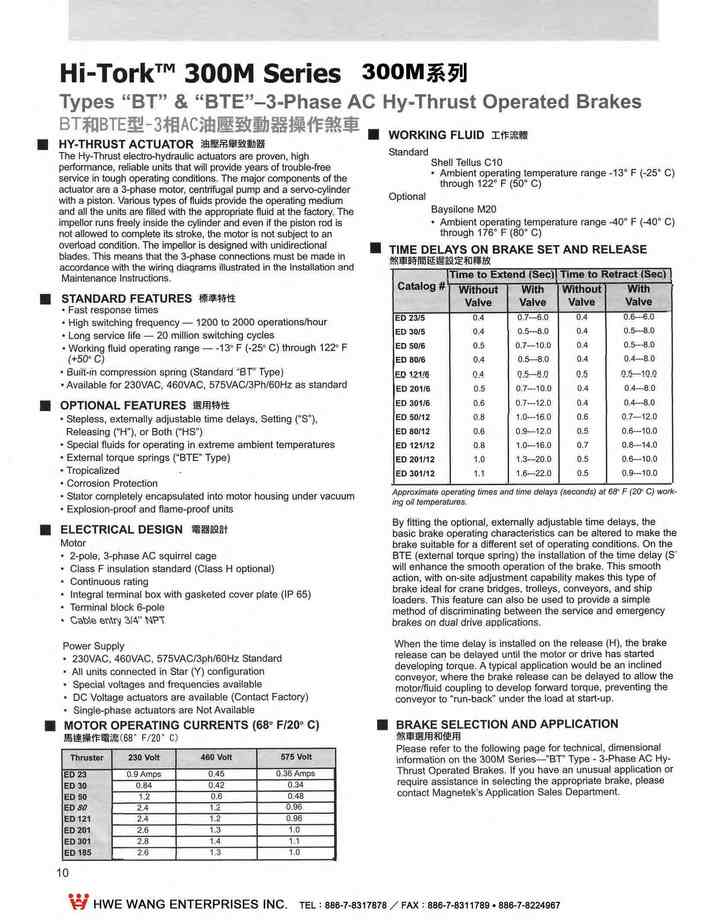
HY-THRUST ACTUATOR
The Hy-Thrust electro-hydraulic actuators are proven,high peorman. relìae units that will provide 。f ubel -free ln tωgh operati conditions.The major ∞mponents of the actuator are a 3-phase moω,r centri仙galpump and a servo-cy1inder with a piston. Vastys of ftuids provide the openg medium
and all the units are filled with the appropte ftuid at the factory.The impellor runs freely inside lhe cylinder and even if lhe piston rod is
not allowed 10 ∞mplete its stroke. the motor is not subject to an
ov。ad ∞nditlon. lmpellor is designed with unidirectional blades.This means that the 3-phase ∞nnections must be made in accordance with Ihe wirlng dlagrams lIluslrated in the Installatlon and Maintenance Instructions.
- STANDARD FEATURES
- Fast response tlmes
- High switchlng frequency -1200to 2000 operationsJhour
- Long service life -20 million switching cycles
- Working fluid operating range 一 -13'F(-25'C)through 12.2' F
(+50.C)
- 8ullt-ln compre臼lon spnng (Standard T'" rype)
- AvailabJe for 230VAC,460VAC,575VAC/3Ph/60Hz as standard
- OPTJONAFl EATURES
- Stepless. externally adjustable time deJays Settlng ('S﹒).
ReJeasing ("H"), or Both C"HS.)
Speclalfluids for operating in extreme ambient temperatures- External torque springs ( BTE Type)
- Tropicalized
- Corrosion Protection
- Statorcompletely encapsulated into motor housing under vacuum
- Explosion-proofand flame-proof units
- ElECTRICADl ESJGN 電器訟計
Motor
- 2-pole,3-phase AC squrirelcage
- Class F lnsulation slandard (Class H optional)
- Continuous ratIng
- Integra川ermlnal box wlth gasketed cover plate (IP 65)
,Terminal block 6-pole
、Cabe en '4" N'?"í
Power Supply
- 230VAC,460VAC,575VAC/3ph/60Hz Standard
,AII unils connected in Star (Y) configuration
- Specialvoltages and frequencies available
- DC Voltage actuators are available (Contact Factory)
,Single-phase actuators are Not Available
- MOTOR OPERATING CURRENTS (680 F/200 C)馬連續(6作8,' F流120' C)
| ||||||||||||||||||||||||||||||||||||||||||||||||||||||||||||||||
- WORKING FlUID 工作流體
Standard Shell Tellus C10
,Ambient operating lemperature range _130 F (-25'C)through 1220 F (50'c)
Baysllone M20
- Ambient operating tempe間划re range -40'F (-40'C)
through 1760 F (800 C)
- TIME DELAYS ON BRAKE SET AND RElEASE
T
Catalog#
lme to Extend (Sec)
Tlme to Retract fSecl
Wltho叫With
Wrthout 1 With
Vavl e
Val ve
Valve
Valve
EO 2315
ED 3015
EO 50/6
EO 80/6 ε1)t1.!1i EO 201/6
EO 301/6
EO 50/12
EO 80/12
EO 121112
EO 201 /12
EO 301112
0.4
0.4
0.5
0,4
'2A
0.5
0.6
0.8
0.6
08
1.0
1.1
0.7-6.0
0.5- 8.0
0.7-10.0
O.已-8.0
'2.
0.7-10.0
0.7-12.0
1.0-16.0
0.9-12.0
1。一16.0
1.各-200
1.6-22.0
0.4
0.4
0.4
0.4
β '2.-2
0.4
0.4
0.6
0.5
0.7
0.5
0.5
0.6-6.0
。‘58- .0
0.5-8.0
0.4--8.0
Q.'Qll
D.4-8.0
0.4-8.0
。7-12.0
0.6-10.0
0.8-14.0
0.6-10.0
0.9-一10.0
Ap proxJmaω operatmg tlmes snd Ilme de∞nds) al68、F(20"C)w ,
Ing 01118mperalu,
By fitting the optìonal ,extemally adjustable tíme delays,the basic brake operating characteristics n be altered to make the brake suitable for a different set of operating conditions. On the BTE (extemal 10ue spring) the installation of the time delay (S' will enhance the smooth opera討on of the brake. This smooth
action,with on-site adjustment capabiilty makes this type of brake ldeal for crane bdges. troleys. conveyors,and ship
loaders.This fealure can also be used 10 provide a simple method of discriminatlng between the service and emergency brakes on dual d叫ve appllcatlons.
When Ihe time delay is Installed on the relea (H,) the brake release cal') be delayed until the motor or drive has sed developing torque. A typicle 1 application would be an inclined
∞nveyor. where the brake release can be delayed to allow the
motorlfluld coupling to develop forward torque. preventing the
conveyor to 'run-back" under the load at start-up.
- BRAKE SElECTJON AND APPlICATION
煞車道悶和使用
Please refer to the following page for techni1. dimensional information on the 300M Sr Type - 3-Phase AC Hy
Thrust Operated Brakes. If you have an unusual application or require assistance in selecting the approp吋ate brake,piease contact Magnetek's Application Sales Department.
更多商品
2-11.MBT和MBTE尺寸和額定能力 MBT & MBTE DIMENSIONS AND RATING
2.300M系列鋼廠級鼓式剎車300M Mill Duty Brakes 下載down load 2-3.說明INTRODUCTION 2-4.訂購資料 ORDERING INFORMATION 2-5.訂購資料 ORDERING INFORMATION 2-6.MBE 型直流磁鐵操作剎車 TYPE MBE DC MAGNET OPERATED BRAKES 2-9.MBT 3相AC油壓致動剎車 TYPE MBT 3-PHASE AC HY-THRUST OPERATED BRAKES 2-10.MBT和MBTE 3相AC油壓致動剎車 TYPE MBT & MBTE 3-PHASE AC HY-THRUST OPERATED BRAKES 2-11.MBT和MBTE尺寸和額定能力 MBT & MBTE DIMENSIONS AND RATING 2-12.BM型.油壓(踏板式)剎車Type BM HYDRAULIC (PEDAL) OPERATED BRAKES 2-13.BM型油壓(踏板式)剎車選用和使用 Type BM Selection and Application 2-14.BEM型DC電磁-油壓鼓式剎車 Type BEM DC MAGNETIC-HYDRAULIC OPERATED SHOE BRAKES 2-15.BEM型DC電磁-油壓鼓式剎車 Type BEM DC MAGNETIC-HYDRAULIC OPERATED SHOE BRAKES 2-16.BEM型DC電磁-油壓鼓式剎車尺寸表和額定能力 The Dimensions and Rating of Type BEM SHOE BRAKES 2-17.BTM和BTME油壓-3相AC油壓致動剎車 MTM & BTME HYDRAULIC-3PHASE AC HY-THRUST OPERATED BRAKES 2-18.BTM和BTME油壓-3相AC油壓致動剎車 MTM & BTME HYDRAULIC-3PHASE AC HY-THRUST OPERATED BRAKES 2-19.BTM和BTME油壓致動剎車尺寸表和額定能力 DIMENSIONS & RATING FOR TYPE MTM & BTME AC HY-THRUST BRAKES 2-20.手動油壓剎車系統-BM , BEM , BTM,BTME 型 MANUAL HYDRAULIC BRAKE SYSTEM-TYPE BM , BEM , BTM & MTME BRAKES 2-21.手動油壓剎車系統 MANUAL HYDRAULIC BRAKE SYSTEM 2-22.剎車鼓-ABW型BRAKE WHEELS-TYPE ABW 2-23.聯軸器BRAKE WHEELS COUPLINGS 2-24.聯軸器尺寸表, DIMENSIONS Of BRAKE WHEELS COUPLINGS 2-25.DC電磁剎車整流器和控制器-BE和BEM型 DC MAGNET BRAKE RECTIFIERS/CONTROLLERS 2-26.剎車蓋和保護箱BRAKES COVERS/ENCLOSURES Rating Data AISE-NEMA and General Purpose (Heavy Duty) Fitted wíth Molded No仟Asbestos Linings CA1ALOG BRAKE WHEEL OIAMETER D TORQUE RAT1NGS (LB.FT.) (1) POWER INPUT 仰'ATTS) (3) WK' OF 8RAKE WHEEL (L8.FT.') 8RAKE WHEEL RPM (MAX) 8'RKE SHIP W日GHT (L8S.) TYPE 8T TYPE 8T/E AISE-NEMA GENERAL PURPOSE 58T - E02315C 8" 8T • E023/5C 10" 8T •E02315C • E030/5C 13" 8T - E03015C • E050/6C •E080/6C 可 6"8T • E030/5C • E050/6C -6080)6C • E0121/6C 19"8T • ED80/6C • E0121/ 6C • E0201/6C 2通IUBT •EOßOl6C -60121/6C • E0201/6C • ED301/6C 30" 8T ..E0121/6C • E020可(6C - E0301/6C 5" 8T/E • E023/5 8" 8T/E • E023/6 10" 8T(E • E023/5 .6030/5 13" 8T/E - E030/5 - E050/6 • E080/6 16" 8T/E - E030/5 • E050/6 - 6080/6 • E0121/6 19" 8TIE • E080/6 -ED121/6 - E0201/6 2:" 8TIE •EDßOl6 • E0121/6 - 6020116 .60301/6 30" 8T/E • ED121/6 -6020可16 .60301/6 5" 8" 10司 10" 13' 13- 13' 16" 16" 16' 16' 19' 19' 19' 2:\' 23. 23' 23' 30' 30' 30' r 一 100 200 一 550 一 1000 一 2000 一 4000 一 9000 50 155 220 260 400 550 660 500 750 1150 1400 1500 2100 2650 可750 3000 4000 5000 3500 6750 11000 140 140 140 175 175 190 260 175 190 260 310 260 310 430 250 310 430 530 310 430 530 0.25 1.25 2.80 一 一 一 7420 一 '55.50 一 880.00 一 9400 5870 4700 一 3600 一 一 一 2470 2040 一 一 1340 一 一 70 95 115 125 235 240 450 455 475 960 990 990 可050 1080 1080 1080 1510 1510 1510
2-12.BM型.油壓(踏板式)剎車Type BM HYDRAULIC (PEDAL) OPERATED BRAKES
2.300M系列鋼廠級鼓式剎車300M Mill Duty Brakes 下載down load 2-3.說明INTRODUCTION 2-4.訂購資料 ORDERING INFORMATION 2-5.訂購資料 ORDERING INFORMATION 2-6.MBE 型直流磁鐵操作剎車 TYPE MBE DC MAGNET OPERATED BRAKES 2-9.MBT 3相AC油壓致動剎車 TYPE MBT 3-PHASE AC HY-THRUST OPERATED BRAKES 2-10.MBT和MBTE 3相AC油壓致動剎車 TYPE MBT & MBTE 3-PHASE AC HY-THRUST OPERATED BRAKES 2-11.MBT和MBTE尺寸和額定能力 MBT & MBTE DIMENSIONS AND RATING 2-12.BM型.油壓(踏板式)剎車Type BM HYDRAULIC (PEDAL) OPERATED BRAKES 2-13.BM型油壓(踏板式)剎車選用和使用 Type BM Selection and Application 2-14.BEM型DC電磁-油壓鼓式剎車 Type BEM DC MAGNETIC-HYDRAULIC OPERATED SHOE BRAKES 2-15.BEM型DC電磁-油壓鼓式剎車 Type BEM DC MAGNETIC-HYDRAULIC OPERATED SHOE BRAKES 2-16.BEM型DC電磁-油壓鼓式剎車尺寸表和額定能力 The Dimensions and Rating of Type BEM SHOE BRAKES 2-17.BTM和BTME油壓-3相AC油壓致動剎車 MTM & BTME HYDRAULIC-3PHASE AC HY-THRUST OPERATED BRAKES 2-18.BTM和BTME油壓-3相AC油壓致動剎車 MTM & BTME HYDRAULIC-3PHASE AC HY-THRUST OPERATED BRAKES 2-19.BTM和BTME油壓致動剎車尺寸表和額定能力 DIMENSIONS & RATING FOR TYPE MTM & BTME AC HY-THRUST BRAKES 2-20.手動油壓剎車系統-BM , BEM , BTM,BTME 型 MANUAL HYDRAULIC BRAKE SYSTEM-TYPE BM , BEM , BTM & MTME BRAKES 2-21.手動油壓剎車系統 MANUAL HYDRAULIC BRAKE SYSTEM 2-22.剎車鼓-ABW型BRAKE WHEELS-TYPE ABW 2-23.聯軸器BRAKE WHEELS COUPLINGS 2-24.聯軸器尺寸表, DIMENSIONS Of BRAKE WHEELS COUPLINGS 2-25.DC電磁剎車整流器和控制器-BE和BEM型 DC MAGNET BRAKE RECTIFIERS/CONTROLLERS 2-26.剎車蓋和保護箱BRAKES COVERS/ENCLOSURES The manual pedaloperated. lIy set- spring released shoe brakes (Type "BM") are deslgned 10 meelthe lalest AISE NEMAspecîfitions for mill. crane and other similar heavy-duty applications. The single.ωgged. wheel (slave) cylinder acts directly on the brake anns to apply varìable forceltorque 10 the brake wheel lhrough lhe brake shoes. The simple design provides a long service life wilh a minimum of mainlenance and down time. CONSTRUCTION " The brake base. shoe holders and lhe shoes are manufactured from ductìle iron. Fabricated steellinkages. The unique self-centerlng aclion compensaled fora certaln amount of mlsallgnment In both the horizon他1 and vertìcal axes. AII brake hardware is corroslon resistant. Composite bushlngs utlllzed In all maln pivot polnts. Molded brake IInings are non-asbestos and provide a ∞nstanl coefficient of r叫ction at nonnal operating temperatures. Shoe linlngs are bonded 10 the shoes delivering nearly Iwice the life over riveled or bolted IIners. TYPE 8" BM HYDRAUL!C BRAKE STANDARD FEATURES 標准特性 Manual bleeding syslem. Short pedal slroke for full braking power through the use of a dual action masler cylínder Maximum pedalfo明70pounds一 OSHA uiremenls. Brake shoes are easily dfrom eilher side of brake. Self-aligning shoes prevent wheel drag. Self-aligning shoes for IInlng wear. Equal shoe clearan is automatic -no adjustment is ne ssary. OPTIONAL FEATURES 道用特性 l"lRemole control bleedlng syslem from operalor's 臼 b. DIRECT ACTING WHEEL (SLAVE) CY LlNDER brake so there is no possibìlity of oil from Ihe 1∞se fittings drlpping行1s direct acilng design ellminales lhe addltional wear and mainlenance assoclaled wilh Ihe long cylinder designs. The sel弘 adjusting fealure of Ihe dlrect acting cyllnder provìdes a nstanl. minimum shoe clearance alall times Ihroughoulthe usefullife of the brake shoe IInings. The cylinder ís mounted at the end of Ihe on the brake linings or brake wheels. SELF-ADJUSTING 13 Every lJme Ihe brake is applied.1Iadjusls itself for any wear lhal has laken place. When released the clearance is always the same belween the brake shoe linings and the brake wheel. Thís fealure reduces mainlenance lime and helps 10 íncrease produclivity. SELF-CENTERING 自發中心 The brake shoes are designed 10 easíly pivot on the brake linkages 10 compensale for slight verti 1 cenlering errors belween the brake and lhe wheel. Thls. along with the self-adjustlng features. also allows for sllght ho巾on|nlering erro. If a brake were 10 shíft shghtly alrighlangles 10 the molor shaft or if one of Ihe shoe IIners wears more rapidly lhan the other. the 計iction bolts will slip on lhe base under acluating pressure. reposilioning and cent叫ng the brake 10 Ihe shafUbrake wheel.刊is self-centering fealure a ures longer IIning life and a poslllve braking acllon.
2-13.BM型油壓(踏板式)剎車選用和使用 Type BM Selection and Application
2.300M系列鋼廠級鼓式剎車300M Mill Duty Brakes 下載down load 2-3.說明INTRODUCTION 2-4.訂購資料 ORDERING INFORMATION 2-5.訂購資料 ORDERING INFORMATION 2-6.MBE 型直流磁鐵操作剎車 TYPE MBE DC MAGNET OPERATED BRAKES 2-9.MBT 3相AC油壓致動剎車 TYPE MBT 3-PHASE AC HY-THRUST OPERATED BRAKES 2-10.MBT和MBTE 3相AC油壓致動剎車 TYPE MBT & MBTE 3-PHASE AC HY-THRUST OPERATED BRAKES 2-11.MBT和MBTE尺寸和額定能力 MBT & MBTE DIMENSIONS AND RATING 2-12.BM型.油壓(踏板式)剎車Type BM HYDRAULIC (PEDAL) OPERATED BRAKES 2-13.BM型油壓(踏板式)剎車選用和使用 Type BM Selection and Application 2-14.BEM型DC電磁-油壓鼓式剎車 Type BEM DC MAGNETIC-HYDRAULIC OPERATED SHOE BRAKES 2-15.BEM型DC電磁-油壓鼓式剎車 Type BEM DC MAGNETIC-HYDRAULIC OPERATED SHOE BRAKES 2-16.BEM型DC電磁-油壓鼓式剎車尺寸表和額定能力 The Dimensions and Rating of Type BEM SHOE BRAKES 2-17.BTM和BTME油壓-3相AC油壓致動剎車 MTM & BTME HYDRAULIC-3PHASE AC HY-THRUST OPERATED BRAKES 2-18.BTM和BTME油壓-3相AC油壓致動剎車 MTM & BTME HYDRAULIC-3PHASE AC HY-THRUST OPERATED BRAKES 2-19.BTM和BTME油壓致動剎車尺寸表和額定能力 DIMENSIONS & RATING FOR TYPE MTM & BTME AC HY-THRUST BRAKES 2-20.手動油壓剎車系統-BM , BEM , BTM,BTME 型 MANUAL HYDRAULIC BRAKE SYSTEM-TYPE BM , BEM , BTM & MTME BRAKES 2-21.手動油壓剎車系統 MANUAL HYDRAULIC BRAKE SYSTEM 2-22.剎車鼓-ABW型BRAKE WHEELS-TYPE ABW 2-23.聯軸器BRAKE WHEELS COUPLINGS 2-24.聯軸器尺寸表, DIMENSIONS Of BRAKE WHEELS COUPLINGS 2-25.DC電磁剎車整流器和控制器-BE和BEM型 DC MAGNET BRAKE RECTIFIERS/CONTROLLERS 2-26.剎車蓋和保護箱BRAKES COVERS/ENCLOSURES Please refer below for technical.dimensional informatíon on the 300M Series 一“BM" Type-Hydraulic (Pedal) Operated Brakes. If you have an unusual appli 臼 tion or required assistance in selecting the approprlate brake,please contact Magnetek's Applicatlon Sales Departmenl. Rating Data AISE-NEMA Fitted with molded non-asbestos linings A ISE-NEAtA額定數鑄 CATALOG# BRAKE WHEEL OIAM。ETER BRAKE TORQUE (HYORAULlC) (LB.FT.) PEOAL FORCE (MAXIMUM) (LBS.) WI(2 0F BRAKE WHEEL (LB.阿') BRAKE WHEEL RPM (MAXIMUM) BRAKE SHIP WEIGHT (LBS.) 5" BM(2) 8" BM 10" BM 可 3" BM 16" BM 19" BM 5" 8" 可。" 13" 16" 19鈔 40 100 200 550 1000 2000 70 70 70 70 70 70 0.25 1.25 2.80 12.00 29.50 74.20 9400 5870 4700 3600 2940 2470 45 52 83 180 305 458 (1) Brake selectlon should be based on torque and duty.When braking servlce Is severe,the WK'of lhe load speed Of the brake wheel and maxîmum number of stops per minute should be submitted 10 the factory for recommendalion. (2) AISE-NEMA does not define B 5-inch brake. For serectlon and appllcaUon data refBr to lhe Appllcation Bnd Engineering Data secllon.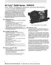
2-14.BEM型DC電磁-油壓鼓式剎車Type BEM DC MAGNETIC-HYDRAULIC OPERATED SHOE BRAKES
2.300M系列鋼廠級鼓式剎車300M Mill Duty Brakes 下載down load 2-3.說明INTRODUCTION 2-4.訂購資料 ORDERING INFORMATION 2-5.訂購資料 ORDERING INFORMATION 2-6.MBE 型直流磁鐵操作剎車 TYPE MBE DC MAGNET OPERATED BRAKES 2-9.MBT 3相AC油壓致動剎車 TYPE MBT 3-PHASE AC HY-THRUST OPERATED BRAKES 2-10.MBT和MBTE 3相AC油壓致動剎車 TYPE MBT & MBTE 3-PHASE AC HY-THRUST OPERATED BRAKES 2-11.MBT和MBTE尺寸和額定能力 MBT & MBTE DIMENSIONS AND RATING 2-12.BM型.油壓(踏板式)剎車Type BM HYDRAULIC (PEDAL) OPERATED BRAKES 2-13.BM型油壓(踏板式)剎車選用和使用 Type BM Selection and Application 2-14.BEM型DC電磁-油壓鼓式剎車 Type BEM DC MAGNETIC-HYDRAULIC OPERATED SHOE BRAKES 2-15.BEM型DC電磁-油壓鼓式剎車 Type BEM DC MAGNETIC-HYDRAULIC OPERATED SHOE BRAKES 2-16.BEM型DC電磁-油壓鼓式剎車尺寸表和額定能力 The Dimensions and Rating of Type BEM SHOE BRAKES 2-17.BTM和BTME油壓-3相AC油壓致動剎車 MTM & BTME HYDRAULIC-3PHASE AC HY-THRUST OPERATED BRAKES 2-18.BTM和BTME油壓-3相AC油壓致動剎車 MTM & BTME HYDRAULIC-3PHASE AC HY-THRUST OPERATED BRAKES 2-19.BTM和BTME油壓致動剎車尺寸表和額定能力 DIMENSIONS & RATING FOR TYPE MTM & BTME AC HY-THRUST BRAKES 2-20.手動油壓剎車系統-BM , BEM , BTM,BTME 型 MANUAL HYDRAULIC BRAKE SYSTEM-TYPE BM , BEM , BTM & MTME BRAKES 2-21.手動油壓剎車系統 MANUAL HYDRAULIC BRAKE SYSTEM 2-22.剎車鼓-ABW型BRAKE WHEELS-TYPE ABW 2-23.聯軸器BRAKE WHEELS COUPLINGS 2-24.聯軸器尺寸表, DIMENSIONS Of BRAKE WHEELS COUPLINGS 2-25.DC電磁剎車整流器和控制器-BE和BEM型 DC MAGNET BRAKE RECTIFIERS/CONTROLLERS 2-26.剎車蓋和保護箱BRAKES COVERS/ENCLOSURES The DC MagnelOperated Brakes (Type BE) can be fitted wíth a pedal operated (manual) hydraullc over-ride system.The brake designation then becomes a BEM Type. Thís Iype of brake combines a hydraulic seVsr.'inglease brake wilh a spring setJmagnetically released brake.The BεM Type shoe brake includes all Ihe features of the índividual BE Type DC magnel operated brakes and the BM Type hydraulic (pedal) operated brakes. This hybrid brake complies with all of Ihe relevanlAISE﹒ NEMA ralings and will provide a long service life wilh the minlmum of downlime and maintenance. CONSγRUCTION The brake bas.e,shoe holders and the shoes are manufactured from ductile iron.Fabrlcated steellinkages ﹒The magnet case and armature are made of caslsteel.AII brake hardware is corrosion resistant. Composite bushings utilized in all main pivot points.The“f1oalin卜linkages"provide positive braking action with equal lining wear. MOlded brake linings are non-asbestos and provide a constant coefficient of friction at normal operating lemperatures. Shoe IInings are bonded 10 the shoes dellverlng nearly twice the life over riveted or bolted liners. STANDARD FEATURES 練導特性 Self adjustment of the hydraulic wheel (slave) cylinder to compensate for IIning wear. Top-hinged magnet prevents dirt and debris from building up between the magnet case and the armature. Anti-friction∞mposltebushings utilized ln all main pivot points for Improved lmpaclresistance.Class "F" insulation -εasily replaceable magnet coil-may be replaced withoullhe loss of brake lorque.Watertight coll and terminal box Self-allgnlng brake shoes-prevents wheel drag Emergency brake release Floor mounting • Short pedal slroke for full braking power Ihrough the use 01a dual action master cylinder OPTIONAL FEATURES 選用特性 Class“H"insulationPatented Self-Adjustment for the brake shoes maintains shoe clearance whìle minimizing impact loading of pivot points.Manuallatching brake release lever Armature positíon indlcalor switch Wall and ceiling mounting ∞nfiguratìons (Consult Factory) • Remole control bleeding system from operator's cab OPERATION 線作說明 During normal operation. the continuously rated magnet coil is energized,and the brake is electrìcally released. Shulting downlhe power to the brake will de-energize the magnelcoil allowing lhe lorque sprlng 10 set the brake. The hydraulíc po巾ion of Ihe brake funclions In the same manner and uses the same components as Ihe BM type brakes described on page 13. Wilh Ihe magnet energized. a pedal operated master cylinder assembly mounted in the operator's area,controls brake applicatìon.This arrangement provides the operator with a smoott method of slowing and stopping the crane.The amount of braklng force Is proportlonal10 the amount of force applied to the master cylinder foot pedal. The single actuatlng cylinder acts directly to pull lhe lìnks/brake shoes together.The design eliminates the additional Iinks, pins and extra wear polnts along with the maintenance associated with these items.The cylìnder is mounted below and off 10 one side of the brake so there is no possibilily of oil from loose fiUlngs dripping onlo the brake shoe liners or brake wheels. Note: When considering tIlis Iype 01 brake ror AC suppliconl,CAB/RADIO and CAB/PENDANT appllcallo 圖 OPTIONAL FEATURES 選用特性 Class“H"insulation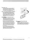
2-15.BEM型DC電磁-油壓鼓式剎車Type BEM DC MAGNETIC-HYDRAULIC OPERATED SHOE BRAKES
2.300M系列鋼廠級鼓式剎車300M Mill Duty Brakes 下載down load 2-3.說明INTRODUCTION 2-4.訂購資料 ORDERING INFORMATION 2-5.訂購資料 ORDERING INFORMATION 2-6.MBE 型直流磁鐵操作剎車 TYPE MBE DC MAGNET OPERATED BRAKES 2-9.MBT 3相AC油壓致動剎車 TYPE MBT 3-PHASE AC HY-THRUST OPERATED BRAKES 2-10.MBT和MBTE 3相AC油壓致動剎車 TYPE MBT & MBTE 3-PHASE AC HY-THRUST OPERATED BRAKES 2-11.MBT和MBTE尺寸和額定能力 MBT & MBTE DIMENSIONS AND RATING 2-12.BM型.油壓(踏板式)剎車Type BM HYDRAULIC (PEDAL) OPERATED BRAKES 2-13.BM型油壓(踏板式)剎車選用和使用 Type BM Selection and Application 2-14.BEM型DC電磁-油壓鼓式剎車 Type BEM DC MAGNETIC-HYDRAULIC OPERATED SHOE BRAKES 2-15.BEM型DC電磁-油壓鼓式剎車 Type BEM DC MAGNETIC-HYDRAULIC OPERATED SHOE BRAKES 2-16.BEM型DC電磁-油壓鼓式剎車尺寸表和額定能力 The Dimensions and Rating of Type BEM SHOE BRAKES 2-17.BTM和BTME油壓-3相AC油壓致動剎車 MTM & BTME HYDRAULIC-3PHASE AC HY-THRUST OPERATED BRAKES 2-18.BTM和BTME油壓-3相AC油壓致動剎車 MTM & BTME HYDRAULIC-3PHASE AC HY-THRUST OPERATED BRAKES 2-19.BTM和BTME油壓致動剎車尺寸表和額定能力 DIMENSIONS & RATING FOR TYPE MTM & BTME AC HY-THRUST BRAKES 2-20.手動油壓剎車系統-BM , BEM , BTM,BTME 型 MANUAL HYDRAULIC BRAKE SYSTEM-TYPE BM , BEM , BTM & MTME BRAKES 2-21.手動油壓剎車系統 MANUAL HYDRAULIC BRAKE SYSTEM 2-22.剎車鼓-ABW型BRAKE WHEELS-TYPE ABW 2-23.聯軸器BRAKE WHEELS COUPLINGS 2-24.聯軸器尺寸表, DIMENSIONS Of BRAKE WHEELS COUPLINGS 2-25.DC電磁剎車整流器和控制器-BE和BEM型 DC MAGNET BRAKE RECTIFIERS/CONTROLLERS 2-26.剎車蓋和保護箱BRAKES COVERS/ENCLOSURES VOLTAGES 電壓 Continuously rated, shunt wound coils are avaìlable for a variety of voltages (Contact Factory for details). The shunt wound brake is designed to release on 80% of voltage. The AISE司NEMA torque ratings are obtained with a continuous duty coil at Intermíttent duty torque ratings. Other shunt cons are available for use wlth AC stalìc rectifier control. AC STATIC RECTIFIER OPERATION AC 靜態登流灣自壘作 00 AC powered equipment where customers prefer a DC brake,an AC/DC controller can be provided. This unit includes a transformer,rectifie,r brake contacto,r protective fusing and a static brake control timer board.The standard controller is mounted În a NEMA 3R Enclosur。on a panel for mounting Inside customers' equipment. Standard units are suitable for 230/460/575-3Ph-.60Hz power supplies.For speclal voltages. 什equencies or other applìcations,please contact factory. PATENTED SELF-ADJUSTMENT FEATURE 專利自我詢盤特性 You never need to adjust this brake for lining wear! It adjusts itsel,f no troublesome mechanical linkages,s ar wheels or other devices for brake adjustment are requried. The simple, automat,dependable way In which the adjustment is ac∞mplished is explained in the lIIuslration below. Each lìme the brake is released, the end stop,attached 10 the brake rod,moves slightly 10 the right Ihrough Ihe pivot block,adjust g plates and plale enc/osure. If Ihe brake linings have worn enough so that adjustment is required,the end slop will move tar enough so that an adjusting ρlate can drop from its upper position to ils lower position around the brake rod. Since this adjustíng ρlate is now between the end slop and pivot block, it shortens the e仔ectiveIravel of the brake rod on the application so that the brake is again in correcladjustment.In Ihís way, the brakes se!adjust throughout the Ihickness of the linings or untillinlngs are replaced. This feature delivers increased productivity and decreased maíntenance time. It also protects the entire brake assembly from the ímpact loads that can become excessive as the gap between Ihe shoes and the wheel increases.BRAKE SELECTION AND APPLlCATION Please reter 10Ihe following page tor technlca,l dlmensional Info何natlon on the 300M Series "BEM"- DC Magnetic Hydraulic Operated Brakes. If you have an unusual application or require assistance in selecting the approprlale brake,please conlaclMagnelek's Appllcation Sales Depamenl.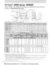
2-16.BEM型DC電磁-油壓鼓式剎車尺寸表和額定能力The Dimensions and Rating of Type BEM SHOE BRAKES
2.300M系列鋼廠級鼓式剎車300M Mill Duty Brakes 下載down load 2-3.說明INTRODUCTION 2-4.訂購資料 ORDERING INFORMATION 2-5.訂購資料 ORDERING INFORMATION 2-6.MBE 型直流磁鐵操作剎車 TYPE MBE DC MAGNET OPERATED BRAKES 2-9.MBT 3相AC油壓致動剎車 TYPE MBT 3-PHASE AC HY-THRUST OPERATED BRAKES 2-10.MBT和MBTE 3相AC油壓致動剎車 TYPE MBT & MBTE 3-PHASE AC HY-THRUST OPERATED BRAKES 2-11.MBT和MBTE尺寸和額定能力 MBT & MBTE DIMENSIONS AND RATING 2-12.BM型.油壓(踏板式)剎車Type BM HYDRAULIC (PEDAL) OPERATED BRAKES 2-13.BM型油壓(踏板式)剎車選用和使用 Type BM Selection and Application 2-14.BEM型DC電磁-油壓鼓式剎車 Type BEM DC MAGNETIC-HYDRAULIC OPERATED SHOE BRAKES 2-15.BEM型DC電磁-油壓鼓式剎車 Type BEM DC MAGNETIC-HYDRAULIC OPERATED SHOE BRAKES 2-16.BEM型DC電磁-油壓鼓式剎車尺寸表和額定能力 The Dimensions and Rating of Type BEM SHOE BRAKES 2-17.BTM和BTME油壓-3相AC油壓致動剎車 MTM & BTME HYDRAULIC-3PHASE AC HY-THRUST OPERATED BRAKES 2-18.BTM和BTME油壓-3相AC油壓致動剎車 MTM & BTME HYDRAULIC-3PHASE AC HY-THRUST OPERATED BRAKES 2-19.BTM和BTME油壓致動剎車尺寸表和額定能力 DIMENSIONS & RATING FOR TYPE MTM & BTME AC HY-THRUST BRAKES 2-20.手動油壓剎車系統-BM , BEM , BTM,BTME 型 MANUAL HYDRAULIC BRAKE SYSTEM-TYPE BM , BEM , BTM & MTME BRAKES 2-21.手動油壓剎車系統 MANUAL HYDRAULIC BRAKE SYSTEM 2-22.剎車鼓-ABW型BRAKE WHEELS-TYPE ABW 2-23.聯軸器BRAKE WHEELS COUPLINGS 2-24.聯軸器尺寸表, DIMENSIONS Of BRAKE WHEELS COUPLINGS 2-25.DC電磁剎車整流器和控制器-BE和BEM型 DC MAGNET BRAKE RECTIFIERS/CONTROLLERS 2-26.剎車蓋和保護箱BRAKES COVERS/ENCLOSURES CATALOG # BRAKE WHEEL DIAMETER 。 TORQUE RATING (LB.FT.) 們} WI(1 。F BRAKE WHEEL (LB.FT乃 BRAKE W刊EEL RPM (MAX) BRAKE SHIP WEIGHT (LBS.) SHUNT RECTIFIER OPERATED CONTINUOUS (8.HOUR) DUTY 8-HOUR (100% 。υTY) HI-SPE印 FORCED 8-HOUR (100% DUTY CYCLE) (2) 8.HOUR (100% DUTY) HI.SPEED FORCED (2) SPRING HYD SPRINGI HYD SPRING HYD SPRINGI HYD 5" BEM (3) 8"8EM 10" BEM 13" BEM 16" 8EM 19" 8EM 5" 8" 10" 13" 16" 19" 30 75 150 400 750 1500 40 100 200 550 1000 2000 40 100 200 550 1000 2000 30 75 150 400 750 1500 40 100 200 550 1000 2000 40 100 200 550 1000 2000 ,25 28U 12.00 29.50 74.20 9400 5870 4700 3600 2940 2470 113 150 位4 438 715 "95 Rating Data for General Purpose (Heavy Duty) Filted with Molded Non-Asbestos llnmgs 5" BEM 8"8EM 10" BEM 13" BEM 16" BEM 19" BEM 5" 8" 10" 13" 16" 19" 40 100 200 550 1∞。 2000 40 120 240 660 12∞ 2650 40 1∞ 2∞ 550 1∞。 2∞。 40 100 2∞ 550 1000 2∞。 40 120 240 660 12∞ 2650 40 100 200 550 100。 20∞ 0.25 1 25 28 12 29.5 742 9400 5870 4700 狗。。 2940 2470 113 150 224 438 715 1195 RATINGS SHOWN FOR 8-HOUR ARE THE THERMAL RATINGS OF THE COll THE TOROUE RATINGS APPlYAT A WORN lINING CONDITION DEFINED AS THE POINT WHERE THE BRAKE RE.ADJUSTS OR WHERE ADJUSTMENr IS REOUIRED AS RECOMMENDED BY THE BRAKE OPERATING INSTRUCT10NS (1) Servlωor Brake selechOn '5 based on lorque and duty. Wl1en braking,lhe WR of Ihe 10ad speed of l1e brake wheeland maxlmum numbor Or SIOps pcr mmute should be submiUed lhe ctOIY for re∞mmendation (2) Recflflor opc叫“ brakes are used wltl1 an AC power urce and are pmvlded wlth DC 51'soωils. Maxlnlum 7 'hopelions per fllllute (3) AlSE.NEMA d06S not deflne a 5.lnoh brake. For selOClon and appllcallon dflia reter 10 Appllcahon and E f1glneering SDcllon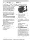
2-17.BTM和BTME油壓-3相AC油壓致動剎車MTM & BTME HYDRAULIC-3PHASE AC HY-THRUST OPERATED BRAKES
2.300M系列鋼廠級鼓式剎車300M Mill Duty Brakes 下載down load 2-3.說明INTRODUCTION 2-4.訂購資料 ORDERING INFORMATION 2-5.訂購資料 ORDERING INFORMATION 2-6.MBE 型直流磁鐵操作剎車 TYPE MBE DC MAGNET OPERATED BRAKES 2-9.MBT 3相AC油壓致動剎車 TYPE MBT 3-PHASE AC HY-THRUST OPERATED BRAKES 2-10.MBT和MBTE 3相AC油壓致動剎車 TYPE MBT & MBTE 3-PHASE AC HY-THRUST OPERATED BRAKES 2-11.MBT和MBTE尺寸和額定能力 MBT & MBTE DIMENSIONS AND RATING 2-12.BM型.油壓(踏板式)剎車Type BM HYDRAULIC (PEDAL) OPERATED BRAKES 2-13.BM型油壓(踏板式)剎車選用和使用 Type BM Selection and Application 2-14.BEM型DC電磁-油壓鼓式剎車 Type BEM DC MAGNETIC-HYDRAULIC OPERATED SHOE BRAKES 2-15.BEM型DC電磁-油壓鼓式剎車 Type BEM DC MAGNETIC-HYDRAULIC OPERATED SHOE BRAKES 2-16.BEM型DC電磁-油壓鼓式剎車尺寸表和額定能力 The Dimensions and Rating of Type BEM SHOE BRAKES 2-17.BTM和BTME油壓-3相AC油壓致動剎車 MTM & BTME HYDRAULIC-3PHASE AC HY-THRUST OPERATED BRAKES 2-18.BTM和BTME油壓-3相AC油壓致動剎車 MTM & BTME HYDRAULIC-3PHASE AC HY-THRUST OPERATED BRAKES 2-19.BTM和BTME油壓致動剎車尺寸表和額定能力 DIMENSIONS & RATING FOR TYPE MTM & BTME AC HY-THRUST BRAKES 2-20.手動油壓剎車系統-BM , BEM , BTM,BTME 型 MANUAL HYDRAULIC BRAKE SYSTEM-TYPE BM , BEM , BTM & MTME BRAKES 2-21.手動油壓剎車系統 MANUAL HYDRAULIC BRAKE SYSTEM 2-22.剎車鼓-ABW型BRAKE WHEELS-TYPE ABW 2-23.聯軸器BRAKE WHEELS COUPLINGS 2-24.聯軸器尺寸表, DIMENSIONS Of BRAKE WHEELS COUPLINGS 2-25.DC電磁剎車整流器和控制器-BE和BEM型 DC MAGNET BRAKE RECTIFIERS/CONTROLLERS 2-26.剎車蓋和保護箱BRAKES COVERS/ENCLOSURES The BT (and BTE) type. 3-phase AC shoe brakes described on page 10 n be fitted with a pI operated (manual) hydraulic override system. This type of brake mblnes a hydraulic seUspring release brake with a spring seUelectrically released brake. These brakes retain I of the features and characteristics o( the individual type BT and BTE 3-phase AC Hy-Thrust Operated brakes and BM Hydraulic brakes. Thís hybrid brake complies with alf of the relevant AISE-NEMA ratings and wilf provide a long service life wilh minimal downtime and maintenance. OPERATION 操作 During normal opera!ion the ∞ntinuously rated Hy-Thrust Actuator is energized and !he brake is electrically released.Shutting down Ihe power to the brake wilf de-energize the actuator alfowlngIhe torque spring 10 se!Ihe brake. A stop butlon localed ln Ihe cab be used 10 de-energlze the brake to provide an emergency stop function should the hydraufic system , The operalor can apply torque 10 the brake wheel through the hydrauflc foot pedal. over-ding the electIf y released actuator.The amount of braking force/torque is propoional lo the amount of force applled to the foolpedal. The hydraullc for crealed is transmitted lo the double acling Wheel(Srave) cyllnder. which acls díreclfy on the brake links/brake shoes forcing them togelher.This brake combination provides the operator wilh a smooth method of slowing and slopping plus an emergency stopping and parking brake. When fitted wilh Ihe adjustable tíme delay on Ihe setting stroke. the external torque spring and the manual pedal operaled over.ride provides a simple.elective and inexpensive alternative to the air/hydraulic or powered hydrauflc systems cornmonly used for dual con!rolled Cab/Radio or Cabl Pendanlcranes. STANDARD FEATURES 標準特性 ﹒Internal torque springs-Type BTM Main plvot polnts are fitted with antl-frictlon composile bushings. Repla able. waterproof Hy-ThruslActuator Brake shoes are self-aligning. Convenienl manual adjuslment for torque and linlng wear Manual release lever Floormounting TYPE 10" BTME-Ed/5S AC HY-THRUST BRAKE OPTIONAFl EATURES 戀問特性 External lorque springs-TypeBTME 1imedelays on brake setling (.S") and release SeladJustment for IIning wear Hydraulic pedal operaled manual over-ride systems Power assist hydraulic over-desystems Walf and ceifing mounting (ContaclFactory) TORQUE ADJUSTMENT OPTIONS The standard Type "BTM" (Intemal lorque spring): Torque spng compressíon rating Is fixed wilhín the th川sler. PrE←se!torquesetlíng provided by pull rod pivot pin locations (3). Torque may be reduced to 60% of maximum rating. The optional Type TME" (External torque spring); Provides stepless toue adjustment Torque adjustment llIade by rotatlng the nulaωpthe spng tube assembly. Torque may be reduced to 40% of maxlmum ratlng. The actual settina can be read on the calíbrated torque indicalor (C.T.I.) located in the side of the spring tube assembly. SElF-ADJUSTING FOR lINING WEAR 來令磨耗自費銷量直 Both the "BT" and lhe "BTε" Iype actuator brakes be fitted with an optional device which au!omatically compensates for Ifning wear throughout th full thickness life of the linings. The selιadjusting feature consists of a one- way operaling clutch.mounted on a special pull-rod,which replaces Ihe standard plill-rod assembly. As the brake Ifnlngs wea,r the actuator stroke increases. This increased movemenlwifl cause a small arm mounted on lhe brake finkages to rote the clUlch ( pull-rod assembly a few degrees.This rotatíon draWs the brake armS slightiy closer togetheι ∞mpensating for the wear in Ihe brake shoe finings. The optional selιadjusting feature eliminales the time requlred 10 manualfy adjuslthe linkages for brake shoe lining wear. It does not reduce or ellminate the planned maintenance inspections as recommended in the OperatTon and Maintenance manual provÎded with lhe brake.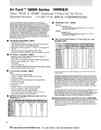
2-18.BTM和BTME油壓-3相AC油壓致動剎車MTM & BTME HYDRAULIC-3PHASE AC HY-THRUST OPERATED BRAKES
2.300M系列鋼廠級鼓式剎車300M Mill Duty Brakes 下載down load 2-3.說明INTRODUCTION 2-4.訂購資料 ORDERING INFORMATION 2-5.訂購資料 ORDERING INFORMATION 2-6.MBE 型直流磁鐵操作剎車 TYPE MBE DC MAGNET OPERATED BRAKES 2-9.MBT 3相AC油壓致動剎車 TYPE MBT 3-PHASE AC HY-THRUST OPERATED BRAKES 2-10.MBT和MBTE 3相AC油壓致動剎車 TYPE MBT & MBTE 3-PHASE AC HY-THRUST OPERATED BRAKES 2-11.MBT和MBTE尺寸和額定能力 MBT & MBTE DIMENSIONS AND RATING 2-12.BM型.油壓(踏板式)剎車Type BM HYDRAULIC (PEDAL) OPERATED BRAKES 2-13.BM型油壓(踏板式)剎車選用和使用 Type BM Selection and Application 2-14.BEM型DC電磁-油壓鼓式剎車 Type BEM DC MAGNETIC-HYDRAULIC OPERATED SHOE BRAKES 2-15.BEM型DC電磁-油壓鼓式剎車 Type BEM DC MAGNETIC-HYDRAULIC OPERATED SHOE BRAKES 2-16.BEM型DC電磁-油壓鼓式剎車尺寸表和額定能力 The Dimensions and Rating of Type BEM SHOE BRAKES 2-17.BTM和BTME油壓-3相AC油壓致動剎車 MTM & BTME HYDRAULIC-3PHASE AC HY-THRUST OPERATED BRAKES 2-18.BTM和BTME油壓-3相AC油壓致動剎車 MTM & BTME HYDRAULIC-3PHASE AC HY-THRUST OPERATED BRAKES 2-19.BTM和BTME油壓致動剎車尺寸表和額定能力 DIMENSIONS & RATING FOR TYPE MTM & BTME AC HY-THRUST BRAKES 2-20.手動油壓剎車系統-BM , BEM , BTM,BTME 型 MANUAL HYDRAULIC BRAKE SYSTEM-TYPE BM , BEM , BTM & MTME BRAKES 2-21.手動油壓剎車系統 MANUAL HYDRAULIC BRAKE SYSTEM 2-22.剎車鼓-ABW型BRAKE WHEELS-TYPE ABW 2-23.聯軸器BRAKE WHEELS COUPLINGS 2-24.聯軸器尺寸表, DIMENSIONS Of BRAKE WHEELS COUPLINGS 2-25.DC電磁剎車整流器和控制器-BE和BEM型 DC MAGNET BRAKE RECTIFIERS/CONTROLLERS 2-26.剎車蓋和保護箱BRAKES COVERS/ENCLOSURES TheHy吊 lrust electro-hydraulic actualors are proven cen!rifugalpump and a servo-cylinder wilh apiston. Varioul!lypes of fluids provide ttie operaUng medium and all the units are filled with the app的priate fluid althelactofY. The motor is nolsubject 10 an overloadcondition,The impellor is designed with unidireclional blades.This means that the 3-phase cOnnections muslbe made in a∞ordance wlth the wiring diagrams iIIus抽ted in the Installation and Maintenance Instructions. STANDARD FEATURES 樣準特性 Faslresponse times Hlgh swilching frequency-120010 2000 operations per hour(50.C.)Long service IIf,←20million switching cycles VVorking Huid operaling range -13.F (﹒鈞。C) through 122.F Built in ∞mpressionspring (Standard "8T" Type) OPTIONA,460VAC,S75VAC/3ph/60Hz as staJ1dard Iepless,extemallyadjuslablelimedelays.Sel1lng("S") , Releasing , or Both ("HS") Special Huids for operatlng In extreme ambient temperalures Exlemal torque sprlngs ("BTE" Type) Tropicarízed Corroslon protection Stalor∞mplelelyen臼psulated intomotor housing under vacuum Explosion-proof and f1ame-proofunits ELECTRICAL DESIGN 電總設計 Motor 2-pole,3-phase AC squirrel cage Class ' P insulation standard (Class "H" optional) Continuous rating Inlegral termlnal box with gasketed cover plate (IP 65) Terminal block 6-pole Cable entry Y: NPT Power Supply 230VAC,460VAC,575VAC/3ph/60Hz standard AII uni俗 connected in Star (Y) con訂guration SpeciaJ vollages and frequencies available DC VOltage actuators are avallable (Contact Factory) Single-phase actuators are nolavailable MOTOR OPERATING CURRENTS (680 F/200 C) Thruster 230/3/60 Volts 460/3/60 Volts 575/3/60 Volts ED 23 ED 30 ED 50 ED 80 ED 21 ED 201 ED 301 ED 185 0.88 Amps 0.76 0.86 2.2 2.2 2.4 2.6 2.4 0.44 Amps 0.38 0.43 1.1 1.1 1.2 1.3 1.2 0.38 Amps 0.33 0.37 0.96 0.96 1.2 1.1 1.0 WORKING FLUID 作業流體 Standa Shell Tellus C10 Ambienloperating temperature range -13. F (-25. c) through 122. F (50.C) Optional Baysilone M20 AmbientoIting temperature range -40. F (-40. C) through 176. F (80'C) TIME DELAYS ON BRAKE SETTING AND RELEASE 煞車延遍設定和緣故 Catal09 # Time to Extend (5ec) Tíme to Retract (Sec) Wlthout Valve Wlth Valve Wlthout VaJve Wlth Valve ED 23/5 ED 30/5 ED 50/6 ED 80/6 ED 121/6 ED 201/6 ED 301 /6 ED 50/12 ED 80/12 ED 12/12 ED 201/12 。01/ 12 0.4 0,4 0.5 0,4 0.4 0.5 0,6 0.8 0.6 0.8 1.0 1.1 0.7-6.0 0.5-8,0 0.7-10,0 8.0 8.0 0.7-10,0 0,7-12.0 1,0-16.0 0.9-12,0 1.0-16.0 1.3-20.0 1.6-22.0 0.4 0.4 0.4 0.4 0.5 0.4 0.4 0.6 0.5 0.7 0.5 0.5 0.6-6.0 0.5-8,0 0.5-8.0 0.4-8.0 0.5-10.0 0.4-8.0 08.4.‘0 0.7-12.0 0.6-10.0 0.8-14.0 0.6-10,0 0.9-10.0 Approximate operatlng Umes and t1me delays (seconds) 。f (20' C) work1ng 。tieI mpera this lype if brake Ideal for crane bdges,olleys,nveyors. and ship loaders,This feature also be used to prode a simple melhod oftheb.issmtl1 action,on-site uslmenlbllily ,makesBy fitting the optlonaJ, extemally adìuslable time delays,the basic brake operating characteristics n be altered 10 make lhe brake suble for a different t ofoting nditions. On the BTE (extemal torque spring) the InsUation of the tìme delay (S) wîll enhance the sm thotion of discminating belween the service and emergency brakes on dualdrive applions.lypi1 applicatìon WOUld be an inclined nveyor,were the brake release n be delayed to allow the molorlfluid uplíng to develop forward torque、preventing nveyor "run-back" under load alsta.rt-Up.When the time delay is install on the ease (H), the brake release n be delay. until the motor or dve has started developíng to RAKE.SELE:CrIONANDPPLICATol.N Please refer to the following page for technica,l dimenslonal infomatior on the 300M Series-"BT" Type-3-Phase AC Hy-Thrust Operated Brakes. If you have an unusual application or rèquire assistance in selecting the appropriate brake please contact Magnetek's Application Sales Dèpartmen