1-3-5.SAF-T-BAR T型電軌(T SERIES CONDUCTOR)
 點擊圖片放大
1-3-5.SAF-T-BAR T型電軌(T SERIES CONDUCTOR)
1.C&W電軌系統(SAF-T-BAR)新目錄
1-1.SAF-T-BAR C型電軌(C SERIES CONDUCTOR) 下載down load
1-2.SAF-T-BAR H型電軌(H SERIES CONDUCTOR) 下載down load
1-3.SAF-T-BAR T型電軌(T SERIES CONDUCTOR) 下載down load
1-4.INSUL-8 8字型電軌(INSUL-8 CONDUCTOR) 下載down load
1-5.INSUL-8側向8型電軌(INSUL-8 SIDE CONTACT CONDUCTOR BAR) 下載down load
1-6.CLUSTER電軌CLUSTER BAR 下載down load
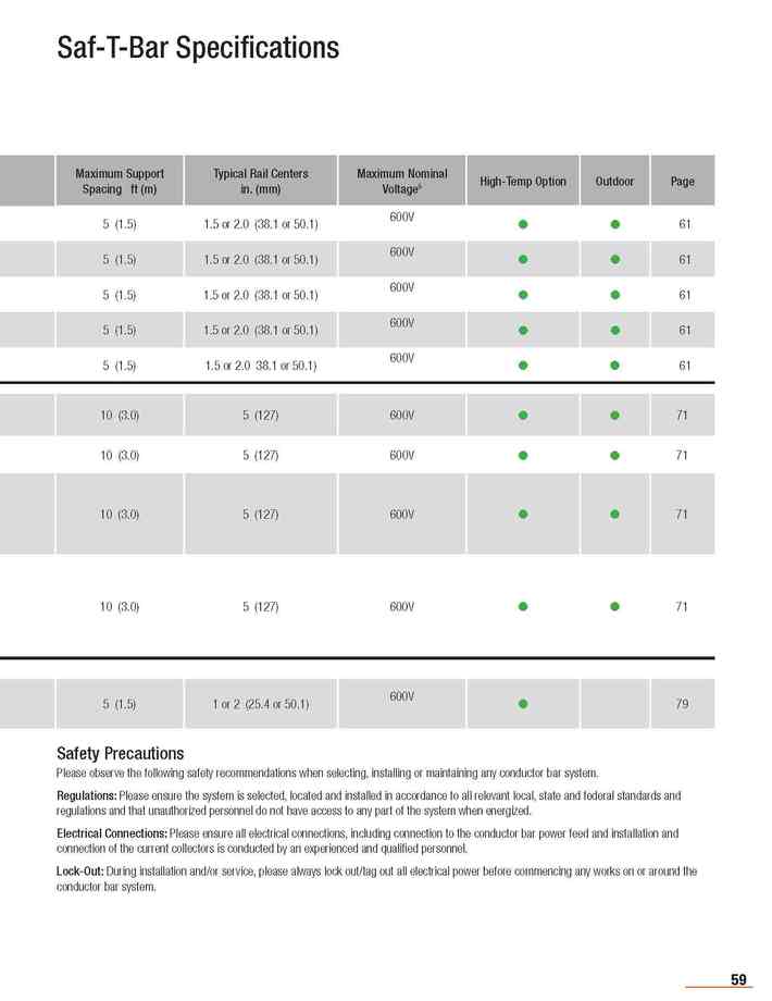
Safety Precautions
Please observe the following safety recommendations when selecting, installing or maintaining any conductor bar system.
Regulations: Please ensure the system is selected, located and installed in accordance to all relevant local, state and federal standards and regulations and that unauthorized personnel do not have access to any part of the system when energized.
Electrical Connections: Please ensure all electrical connections, including connection to the conductor bar power feed and installation and connection of the current collectors is conducted by an experienced and qualified personnel.
Lock-Out: During installation and/or service, please always lock out/tag out all electrical power before commencing any works on or around the conductor bar system.
更多商品
1-3-4.SAF-T-BAR T型電軌(T SERIES CONDUCTOR)
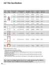
1.C&W電軌系統(SAF-T-BAR)新目錄 1-1.SAF-T-BAR C型電軌(C SERIES CONDUCTOR) 下載down load 1-2.SAF-T-BAR H型電軌(H SERIES CONDUCTOR) 下載down load 1-3.SAF-T-BAR T型電軌(T SERIES CONDUCTOR) 下載down load 1-4.INSUL-8 8字型電軌(INSUL-8 CONDUCTOR) 下載down load 1-5.INSUL-8側向8型電軌(INSUL-8 SIDE CONTACT CONDUCTOR BAR) 下載down load 1-6.CLUSTER電軌CLUSTER BAR 下載down load Maximum voltage for all Series - 600 volts. 1 Nominal current is based on 30°C and 100% duty cycles. 2 Weight includes both the bar material and the insulating cover. 3 AC impedance is measured in ohms/ft based on 30°C and the largest typical bar centers. Please adjust as necessary for other ambient temperatures and/or bar centers. 4 DC resistance is measured in ohms/ft based on 30°C and the largest typical bar centers. Please adjust as necessary for other ambient temperatures and/or bar centers. 5 Maximum nominal voltage is based on standard insulation materials and spacing. For higher voltage applications, please consult the factory.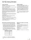
1-3-3.SAF-T-BAR T型電軌(T SERIES CONDUCTOR)
1.C&W電軌系統(SAF-T-BAR)新目錄 1-1.SAF-T-BAR C型電軌(C SERIES CONDUCTOR) 下載down load 1-2.SAF-T-BAR H型電軌(H SERIES CONDUCTOR) 下載down load 1-3.SAF-T-BAR T型電軌(T SERIES CONDUCTOR) 下載down load 1-4.INSUL-8 8字型電軌(INSUL-8 CONDUCTOR) 下載down load 1-5.INSUL-8側向8型電軌(INSUL-8 SIDE CONTACT CONDUCTOR BAR) 下載down load 1-6.CLUSTER電軌CLUSTER BAR 下載down load System Components: Conductor Bar: Selected to meet ampacity, voltage drop, duty cycle, environmental, and application requirements. Rail Joints : Required for each connection, unless the joint is pre-mounted to the bar - Series C and Series T only. Hanger/Anchor Clamps: Must be installed at the spacing specified in this catalog. Anchor points must be determined and set according to the expansion of the system. Hangers must be installed at least 6"(152 mm) from any rail joint or power feed to allow for adequate system expansion. Support Arms: Support arms are required at each hanger clamp location and must be of sufficient strength to ensure safe suspension of the conductor bar system. Power Feeds: The ideal location for a single power feed is the center point of the system to yield the minimum voltage drop. A minimum of one power feed is required per pole. Expansion Sections: Expansion sections are required for installations beyond certain total system lengths - See Pg. 65. End Caps: End caps are required to insulate the system at the rail ends. Collectors: Collectors must be selected to meet the amperage requirements of crane/machine and the related duty cycle of the application. Collector Towing Arm: Is required for each set of current collectors and is required to tow the collector assembly. National Electric Code Ampacity Requirements For one motor, use 100% of motor nameplate full load ampere rating. For multiple motors on a single crane or hoist, the minimum circuit ampacity of the power supply conductors on a crane or hoist shall be the nameplate full load ampere rating of the largest motor or group of motors for any single crane motion, plus 50% of the nameplate full load ampere rating of the next largest motor or group of motors. For multiple cranes and/or hoists supplied by a common conductor system, compute the motor minimum ampacity for each crane as in step (2), add them together and multiply the sum of the demand factor from the following table: Number of cranes Demand factor 2 .95 3 .91 4 .87 5 .84 6 .81 7 .78 For constant loads such as magnets, lights, and air conditioners, etc., plus high duty cycles, use full load amperage, in selecting conductor size. System Calculations The Specification Data Sheets on pages 6-7 will help you collect information about your application. Also, see Pgs. 83-88 for other considerations that will help you choose the correct conductor bar system for your application. Please also refer to your relevant local, state/provincial, and federal regulations to make sure that the correct material is selected. In the USA, refer to calculation methods used in NEC 610-14(e). For constant loads such as magnets, lights, and air conditioners, etc., plus high duty cycles, use full load amperages to select conductor size. Once these values are determined, depending upon the ambient temperature, apply ampacity correction factors (as per table 610.14(A). Voltage Drop Calculation - See also Pgs. 84 and 87. As most motors are designed to operate with a 2.5% to 5% voltage drop, divide volts lost by line voltage to determine if a larger conductor or additional feed points are required. See tables for values Z and R. 3 phase AC Volts lost = 1.73 x Z x Length in feet from feed x Ampere load 1 phase AC Volts lost = 2 x Z x Length in feet from feed x Ampere load DV Volts lost = 2 x R x Length in feet from feed x Ampere load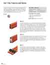
1-3-2.SAF-T-BAR T型電軌(T SERIES CONDUCTOR)
1.C&W電軌系統(SAF-T-BAR)新目錄 1-1.SAF-T-BAR C型電軌(C SERIES CONDUCTOR) 下載down load 1-2.SAF-T-BAR H型電軌(H SERIES CONDUCTOR) 下載down load 1-3.SAF-T-BAR T型電軌(T SERIES CONDUCTOR) 下載down load 1-4.INSUL-8 8字型電軌(INSUL-8 CONDUCTOR) 下載down load 1-5.INSUL-8側向8型電軌(INSUL-8 SIDE CONTACT CONDUCTOR BAR) 下載down load 1-6.CLUSTER電軌CLUSTER BAR 下載down load The Saf-T-Bar line of conductor bar products was originally manufactured by the Howell Corporation and is now part of the Conductix-Wampfler product family. Saf-T-Bar is designed to provide customers with a cost effective, yet highly reliable system for the transmission of electrical energy. Each system is designed with simplicity and reliability in mind. The performance of the product line has been proven in the field for over 30 years. Saf-T-Bar® is Ideal for: Small to Large Cranes • Hoists Conveyors • ASRS Systems (T Series) Monorails and Trolleys • Other Moving Equipment Current range @ 600 Volts Maximum: C Series: 90A, 110A, 250A, 300A, 350A H Series: 500A, 750A, 1000A, 1500A T Series: 65A Maximum Speed: 900 ft/min (274 meters/min) Series C The Series C range of conductor bars is available in capacities from 90 amps through toing pressure. The push-pin joint system requires no loose hardware to install. C Series bars are available with standard rigid PVC insulation, or optional medium-heat Lexan or high-heat fiberglass insulation. Available accessories include single or tandem collectors, various single or multi-pole hanger clamps (3 or 4 pole), isolation sections, and expansion sections for longer runs.350 amps and can be mounted in any plane. The "C"-shaped metal guideway provides positive tracking of the collector shoe within the profile of the bar; the shoe will track with or without the cover. The flat contact surface of the bar and copper graphite shoe yields minimal shoe wear. Skin-tight insulation runs cooler and will not deform under clamp- Series H The Series H Conductor Bar has the highest current rating of the Saf-T-Bar lines, available in four amperages; 500, 750, 1000, and 1500 amps. Each of the profiles are constructed of extruded aluminum with an integrated stainless steel contact channel rolled into aluminum material to ensure positive tracking of the collector and optimum collector shoe wear. This series is available with standard or high temperature insulation covers and a vast array of accessories. Series T The T Series system is unique to Conductix-Wampfler and features a captive collector concept resulting in an extremely compact system. The conductor bars are supplied with pre-mounted joints. Using the jointing tool, adjoining rails can be connected quickly and easily. Special spring collectors are constructed of a chromium-copper material which ensures optimized collector wear. Available in 65 amp galvanized steel with a full line of accessories.
1-3-1.SAF-T-BAR T型電軌(T SERIES CONDUCTOR)
1.C&W電軌系統(SAF-T-BAR)新目錄 1-1.SAF-T-BAR C型電軌(C SERIES CONDUCTOR) 下載down load 1-2.SAF-T-BAR H型電軌(H SERIES CONDUCTOR) 下載down load 1-3.SAF-T-BAR T型電軌(T SERIES CONDUCTOR) 下載down load 1-4.INSUL-8 8字型電軌(INSUL-8 CONDUCTOR) 下載down load 1-5.INSUL-8側向8型電軌(INSUL-8 SIDE CONTACT CONDUCTOR BAR) 下載down load 1-6.CLUSTER電軌CLUSTER BAR 下載down load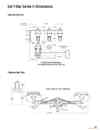
1-2-13.SAF-T-BAR H型電軌(H SERIES CONDUCTOR)
1.C&W電軌系統(SAF-T-BAR)新目錄 1-1.SAF-T-BAR C型電軌(C SERIES CONDUCTOR) 下載down load 1-2.SAF-T-BAR H型電軌(H SERIES CONDUCTOR) 下載down load 1-3.SAF-T-BAR T型電軌(T SERIES CONDUCTOR) 下載down load 1-4.INSUL-8 8字型電軌(INSUL-8 CONDUCTOR) 下載down load 1-5.INSUL-8側向8型電軌(INSUL-8 SIDE CONTACT CONDUCTOR BAR) 下載down load 1-6.CLUSTER電軌CLUSTER BAR 下載down load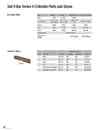
1-2-12.SAF-T-BAR H型電軌(H SERIES CONDUCTOR)
1.C&W電軌系統(SAF-T-BAR)新目錄 1-1.SAF-T-BAR C型電軌(C SERIES CONDUCTOR) 下載down load 1-2.SAF-T-BAR H型電軌(H SERIES CONDUCTOR) 下載down load 1-3.SAF-T-BAR T型電軌(T SERIES CONDUCTOR) 下載down load 1-4.INSUL-8 8字型電軌(INSUL-8 CONDUCTOR) 下載down load 1-5.INSUL-8側向8型電軌(INSUL-8 SIDE CONTACT CONDUCTOR BAR) 下載down load 1-6.CLUSTER電軌CLUSTER BAR 下載down load Type L Series D Series Heat Sink L Series Heat Sink D Series Body 302B 50-901 302B Contact Shoe 300SHP (6") 400SHP (8") 300SHP (6") 400SHP (8") 400SHPHS (x2) 400SHPHS (x2) Spring 300Z 300Z 300Z 300Z Arm 300LP 50-902 300LP 50-902 Spool 1000Q 1000Q 50-906 50-906 Welding cable WR002RD1600 Heat sink as- sembly - - 400YHP-Head 400YHP-Head Capacity (amps) Qty Description Shoe Size Continuous Intermittent Part No. 1 Single 5/8" x 6" 200 300 300SHP 2 Dual 5/8" x 6" 400 600 300SHP 1 Single 5/8 x 8" 300 450 400SHP 2 Dual 5/8 x 8" 600 900 400SHP 1 Single, Heat Sink Design 5/8 x 8" 400 500 400SHPHS 2 Dual, Heat Sink Design 5/8 x 8" 800 1000 400SHPHS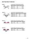
1-2-11.SAF-T-BAR H型電軌(H SERIES CONDUCTOR)
1.C&W電軌系統(SAF-T-BAR)新目錄 1-1.SAF-T-BAR C型電軌(C SERIES CONDUCTOR) 下載down load 1-2.SAF-T-BAR H型電軌(H SERIES CONDUCTOR) 下載down load 1-3.SAF-T-BAR T型電軌(T SERIES CONDUCTOR) 下載down load 1-4.INSUL-8 8字型電軌(INSUL-8 CONDUCTOR) 下載down load 1-5.INSUL-8側向8型電軌(INSUL-8 SIDE CONTACT CONDUCTOR BAR) 下載down load 1-6.CLUSTER電軌CLUSTER BAR 下載down load For collector movement of 2" in direction of contact and ± 1" lateral drift. Description Intermittent Only Continuous or Intermittent Part No. Single arm 300A 200A HA300LS Tandem arm 600A 400A HA600LLS Single arm 450A 300A HA400LS Tandem arm 900A 600A HA800LLS Description Intermittent Only Continuous or Intermittent Part No. Dual Parallel Arm, Single 300A 200A HA300DS Dual Parallel Arm, Tandem 600A 200A HA600DDS Dual Parallel Arm, Single 450A 300A HA400DS Dual Parallel Arm, Tandem 900A 600A HA800DDS For collector movement of 2" in direction of contact and ± 1" lateral drift. Description Intermittent Only Continuous or Intermittent Part No. Single arm 500A 400A HA400LSHS Tandem arm 1000A 800A HA800LLSHS For collector movement of 3" in direction of contact and ± 3" lateral drift Description Intermittent Only Continuous or Intermittent Part No. Single arm 500A 400A HA400DSHS Tandem arm 1000A 800A HA800DDSHS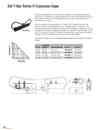
1-2-10.SAF-T-BAR H型電軌(H SERIES CONDUCTOR)
1.C&W電軌系統(SAF-T-BAR)新目錄 1-1.SAF-T-BAR C型電軌(C SERIES CONDUCTOR) 下載down load 1-2.SAF-T-BAR H型電軌(H SERIES CONDUCTOR) 下載down load 1-3.SAF-T-BAR T型電軌(T SERIES CONDUCTOR) 下載down load 1-4.INSUL-8 8字型電軌(INSUL-8 CONDUCTOR) 下載down load 1-5.INSUL-8側向8型電軌(INSUL-8 SIDE CONTACT CONDUCTOR BAR) 下載down load 1-6.CLUSTER電軌CLUSTER BAR 下載down load Expansion Gap assemblies are pre-assembled and ready to be installed between two adjacent sections of rail to compensate for thermal expansion of the rail due to environmental changes and power-generated heat. Each end of the expansion section is attached to its mating rail with a powerfeed type of rail splice. Aluminum conductors will expand one inch in 70 feet per 100o F temperature variation. The Expansion Gap will handle expansions of up to 8". The Expansion Gap assembly is 12" long "closed" and 20" long expanded (with the maximum gap of 8".) The gap is normally set at 4" in an average 600 F environment. An Expansion Gap assembly is required for every 500 feet (or fraction thereof) in system length to handle a 100 degree F maximum temperature variation. A proportional decrease in the 500 foot interval is required for greater temperature variations. Center point of all conductor runs using expansion gaps requires an anchor clamp kit to locate rail settings. For Bar Powerfeeds included Jumpers included Part No. Wt lb (kg) HC500 HA500F # 3/0 x 40" HA500XG-8" 13.0 (5.90) HC750 HA750F Two # 3/0 x 50" HA750XG-8" 13.0 (5.90) HC1000 HA1000F Two # 3/0 x 50" HA1000XG-8" 15.0 (6.80) HC1500 HA1500F Two 350 MC x 50" HA1500XG-8" 20.0 (9.07)