3-5.一般說明GENERAL INDICATION
 點擊圖片放大
3-5.一般說明GENERAL INDICATION
3.重型電纜滑車 HEAVY DUTY CABLE TROLLEY 下載down load
3-3.索引INDEX
3-4.產品介紹INTRODUCTION
3-5.一般說明GENERAL INDICATION
3-6.一般說明GENERAL INDICATION
3-7.托拉鋼索長度 TOWING WIRE ROPE LENGTH
3-8.型號 : 2.333電纜小車、尾夾和主導車 、荷重250KG
REF. 2.333 CABLE TROLLEY
3-9.型號 : 2.333組裝說明 REF. 2.333 GENERAL ARRANGEMENT
3-10.型號 : 2.334荷重能力350KG
REF. 2.334 CABLE TROLLEY 、CAPACITY 350KG
3-11.型號 : 2.334組裝說明REF. 2.334 GENERAL ARRANGEMENT
3-12.型號 : 2.345荷重能力450KG
REF. 2.345 CABLE TROLLEY 、CAPACITY 450KG
3.13.型號 : 2.345組裝圖REF. 2.345 GENERAL ARRANGEMENT
3-14.型號 : 2.346荷重能力500KG
REF. 2.346 CABLE TROLLEY 、CAPACITY 500KG
3-15.型號 : 2.346組裝說明REF. 2.346 GENERAL ARRANGEMENT
3-16.電纜固定夾CLAMPS
3-17.托拉鋼索或鍊條TOWING WIRE ROPE OR CHAIN
3-18.常用備品USUAL SPARE PARTS
3-19.不同工字樑所使用不同滑車輪 TROLLEY WHEEL ON DIFFERENT BEAM
3-20.鳥波林圓形和PVC可繞性電線 FLEXIBLE BUTYL NEOPRENE AND PVC CONDUCTORS
3-21.問卷表QUESTIONNAIRE
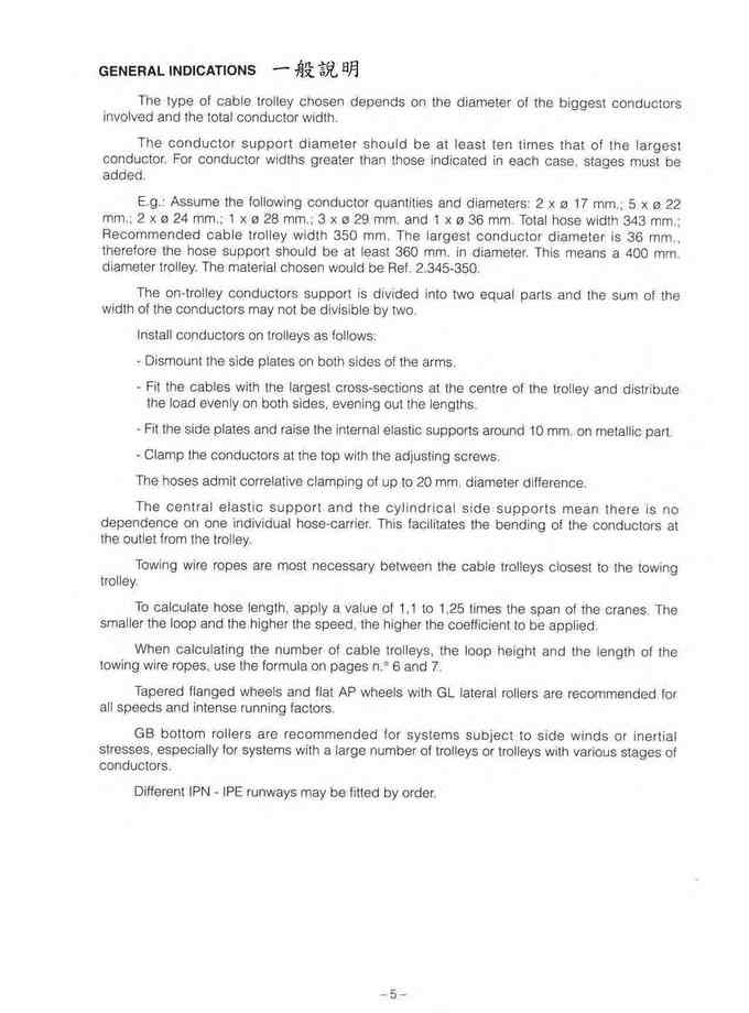
The type of cable trolley chosen depends on the diameter of the biggest conductors involved and the total conductor width.
The conductor sυpport diameter should be at least ten times that of the largest conductor. For conductor widths greater than those indicated in each case ,stages must be added.
E.g.: Assume the following conductor quantities and diameters: 2 x ø 17 mm.; 5 x ø 22 mm.; 2 x ø 24 mm.; 1 x ø 28 mm.; 3 x ø 29 mm. and 1 x ø 36 mm. Total hose width 343 mm.; Recommended cable trolley width 350 mm. The largest conductor diameter is 36 mm., therefore the hose support should be at least 360 mm. in diameter. This means a 400 mm. diameter trolley. The material chosen would be Ref. 2.345-350.
The on-trolley conductors support is divided into two equal parts and the sum of the width of the conductors may not be divisible by two.
Install conductors on trol1eys as fol1ows:
- Dismount the side plates on both sides of the arms.
- Fit the cables with the largest cross-sections at the centre of the trol1ey and distribute the load evenly on both sides, evening out the lengths.
- Fit the side plates and raise the internal elastic supports around 10 mm. on metallic part.
- Clamp the conductors at the top with the adjusting screws.
The hoses admit correlative clamping of up to 20 mm. diameter difference.
The central elastic support and the cylindrlcal side supports mean there is no dependence on one individual hose-carrier. This faci1itates the bending of the conductors at the outlet from the trolley.
Towing wire ropes are most necessary between the cable trolleys closest to the towing trolley.
To calculate hose length, apply a value of 1,1 to 1,25 times the span of the cranes. The smaller the loop and the higher the speed, the higher the coefficient to be applied.
When calculating the number of cable trol1eys, the loop height and the length of the towing wire ropes,use the formula on pages n.O 6 and 7.
Tapered flanged wheels and flat AP wheels with GL lateral rollers are recommended for all speeds and intense running factors.
GB bottom rollers are recommended for systems subject to side winds or inertial stresses,especial1y for systems with a large number of trolleys or trolleys with various stages of conductors.
Different lPN - IPE runways may be fitted by order.
更多商品
3-4.產品介紹INTRODUCTION
3.重型電纜滑車 HEAVY DUTY CABLE TROLLEY 下載down load 3-3.索引INDEX 3-4.產品介紹INTRODUCTION 3-5.一般說明GENERAL INDICATION 3-6.一般說明GENERAL INDICATION 3-7.托拉鋼索長度 TOWING WIRE ROPE LENGTH 3-8.型號 : 2.333電纜小車、尾夾和主導車 、荷重250KG REF. 2.333 CABLE TROLLEY 3-9.型號 : 2.333組裝說明 REF. 2.333 GENERAL ARRANGEMENT 3-10.型號 : 2.334荷重能力350KG REF. 2.334 CABLE TROLLEY 、CAPACITY 350KG 3-11.型號 : 2.334組裝說明REF. 2.334 GENERAL ARRANGEMENT 3-12.型號 : 2.345荷重能力450KG REF. 2.345 CABLE TROLLEY 、CAPACITY 450KG 3.13.型號 : 2.345組裝圖REF. 2.345 GENERAL ARRANGEMENT 3-14.型號 : 2.346荷重能力500KG REF. 2.346 CABLE TROLLEY 、CAPACITY 500KG 3-15.型號 : 2.346組裝說明REF. 2.346 GENERAL ARRANGEMENT 3-16.電纜固定夾CLAMPS 3-17.托拉鋼索或鍊條TOWING WIRE ROPE OR CHAIN 3-18.常用備品USUAL SPARE PARTS 3-19.不同工字樑所使用不同滑車輪 TROLLEY WHEEL ON DIFFERENT BEAM 3-20.鳥波林圓形和PVC可繞性電線 FLEXIBLE BUTYL NEOPRENE AND PVC CONDUCTORS 3-21.問卷表QUESTIONNAIRE CABLE TROLLEYS Formed by a central body made of a single piece of rolled steel. Their design and sturdiness make them ideal for critical ,high-speed and fatigue-prone jobs. Each stage consists of two arms with clamps and an independent support on the central body. AII metal items are galvanized and coated with polyester paint. Nuts and bolts may be galvanized or stainless stee,l which the system is subjected. depending on the conditions to Made with different runway assemblies according to the type of application The wheels are made of hardened steel. The protected bearings are totally sealed on one side,with a rubber retainer in the shaft area. The wheels run on flat or sloping runways. To prevent noise and runway wear at high speeds,a plastic covering is used (Vulkollan) The catalogue shows the runways available. Changes can be made according to the system involved. CLAMPS - TYPE B These are made up of two pre-formed metal sections (galvanized and polyester-coated) which house two elastic bodies which grip and gather the conductors in the loop. CLAMPS - TYPE BF These have the same attributes as TYPE 8, for bundles of flat conductors, plus a window where the remaining hoses are housed with freedom to slide As a general rule we recommend fitting one clamp at the bottom for 1 metre high loops , two c1amps at the sides for 2 metre loops and one at the bottom plus two at the sides for 3 metre loops. When fitting c1amps to the sides of loops ,check that when the loops are gathered in the clamps are not opposite each other to prevent them knocking each other. TOWING WIRE ROPES Formed by 6-8 mm. diameter stranded steel cables with insulated PVC covering with rings and dead-end thimbles: TYPE 下ø-L. Chain rope: TYPE TC-ø-L. These P.v.C. covered wire ropes provide improved corrosion resistance and do not deteriorate the electric conductors. The fitting of towing wire ropes is recommended in all cases,and essential at speeds of more than 40 m./min. For systems working at more than 100 m./min. with frequent changes of direction,TYPE TEP-ø-L elastic towing ropes are used. These are mounted on both sides of the towing wire rope. The number fitted depends on the acceleration and braking of the system. Fitting these elastic towing ropes between trolleys or at least between some of them enables the risk of the electrical conductors deteriorating to be eliminated (speed of up to 210 m./min. can be attained).
3-3.索引INDEX
3.重型電纜滑車 HEAVY DUTY CABLE TROLLEY 下載down load 3-3.索引INDEX 3-4.產品介紹INTRODUCTION 3-5.一般說明GENERAL INDICATION 3-6.一般說明GENERAL INDICATION 3-7.托拉鋼索長度 TOWING WIRE ROPE LENGTH 3-8.型號 : 2.333電纜小車、尾夾和主導車 、荷重250KG REF. 2.333 CABLE TROLLEY 3-9.型號 : 2.333組裝說明 REF. 2.333 GENERAL ARRANGEMENT 3-10.型號 : 2.334荷重能力350KG REF. 2.334 CABLE TROLLEY 、CAPACITY 350KG 3-11.型號 : 2.334組裝說明REF. 2.334 GENERAL ARRANGEMENT 3-12.型號 : 2.345荷重能力450KG REF. 2.345 CABLE TROLLEY 、CAPACITY 450KG 3.13.型號 : 2.345組裝圖REF. 2.345 GENERAL ARRANGEMENT 3-14.型號 : 2.346荷重能力500KG REF. 2.346 CABLE TROLLEY 、CAPACITY 500KG 3-15.型號 : 2.346組裝說明REF. 2.346 GENERAL ARRANGEMENT 3-16.電纜固定夾CLAMPS 3-17.托拉鋼索或鍊條TOWING WIRE ROPE OR CHAIN 3-18.常用備品USUAL SPARE PARTS 3-19.不同工字樑所使用不同滑車輪 TROLLEY WHEEL ON DIFFERENT BEAM 3-20.鳥波林圓形和PVC可繞性電線 FLEXIBLE BUTYL NEOPRENE AND PVC CONDUCTORS 3-21.問卷表QUESTIONNAIRE REFERENCE 2.333 - Cable trolley,End clamp,Towing trolley 8 - Clamps, Towing wire rope, Chain rope, Elastic towing rope 9 REFERENCE 2.334 - Cable trolley,End clamp,Towing trolley 10 - Clamps,Towing wire rope, Chain rope,Elastic towing rope 11 REFERENCE 2.345 - Cable trolley, End clamp, Towing trolley 12 - Clamps,Towing wire rope,Chain rope, Elastic towing rope ., 13 REFERENCE 2.346 - Cable trolley,End clamp, Towing trolley 14 - Clamps,Towing wire rope, Chain rope, Elastic towing rope 1a5uauau7 CLAMPS TYPE 8 AND BF 16 TOWING WIRE ROPES: FIXED AND ELASTIC 17 USUAL SPARE PARTS ., 18 RUNWAY ASSEMBLlES 19 FLEXIBLE BUTYL NEOPRENE AND PVC CONDUCTORS 20 QUESTIONNAIRE , 21 COUNTRIES CONSUMERS OF OUR PRODUCTS 22
3-1.重型電纜滑車 HEAVY DUTY CABLE TROLLEY
3.重型電纜滑車 HEAVY DUTY CABLE TROLLEY 下載down load 3-3.索引INDEX 3-4.產品介紹INTRODUCTION 3-5.一般說明GENERAL INDICATION 3-6.一般說明GENERAL INDICATION 3-7.托拉鋼索長度 TOWING WIRE ROPE LENGTH 3-8.型號 : 2.333電纜小車、尾夾和主導車 、荷重250KG REF. 2.333 CABLE TROLLEY 3-9.型號 : 2.333組裝說明 REF. 2.333 GENERAL ARRANGEMENT 3-10.型號 : 2.334荷重能力350KG REF. 2.334 CABLE TROLLEY 、CAPACITY 350KG 3-11.型號 : 2.334組裝說明REF. 2.334 GENERAL ARRANGEMENT 3-12.型號 : 2.345荷重能力450KG REF. 2.345 CABLE TROLLEY 、CAPACITY 450KG 3.13.型號 : 2.345組裝圖REF. 2.345 GENERAL ARRANGEMENT 3-14.型號 : 2.346荷重能力500KG REF. 2.346 CABLE TROLLEY 、CAPACITY 500KG 3-15.型號 : 2.346組裝說明REF. 2.346 GENERAL ARRANGEMENT 3-16.電纜固定夾CLAMPS 3-17.托拉鋼索或鍊條TOWING WIRE ROPE OR CHAIN 3-18.常用備品USUAL SPARE PARTS 3-19.不同工字樑所使用不同滑車輪 TROLLEY WHEEL ON DIFFERENT BEAM 3-20.鳥波林圓形和PVC可繞性電線 FLEXIBLE BUTYL NEOPRENE AND PVC CONDUCTORS 3-21.問卷表QUESTIONNAIRE
2-22.2330特殊圓形電纜滑車SPECIAL CABLE TROLLEYS 2330
2. C型軌及配件 C PROFILE CABLE TROLLEY 下載down load 2-1.C型軌及電纜滑車 FLEXIBLE ENERGY SUPPLY SYSTEMS THROUGH CABLE TROLLEYS 2-2.2331-1 C型軌及配件PROFILE 2331-1 AND ACCESSORIES 2-3.2331-2 C型軌及配件PROFILE 2331-2 AND ACCESSORIES 2-4.2331-5 C型軌及配件PROFILE 2331-5 AND ACCESSORIES 2-5.2332和2400電纜滑車CABLE TROLLEY 2332 & 2400 2-6.2401和2330電纜滑車CABLE TROLLEY 2401 & 2330 2-7.2331和2400主導滑車 TOWING TROLLEY 2331 & 2400 2-8.2400和2401主導滑車 TOWING TROLLEY 2400 & 2401 2-9.2331接線盒主導滑車 STATION TOWING TROLLEY 2331 2-10.2400尾端夾 END CLAMP 2400 2-11.2338圓形電線特殊滑車 SPECIAL TROLLEY FOR ROUND CABLE 2338 2-12.2324特殊電纜滑車 SPECIAL CABLE TROLLEYS 2324 2-13.安裝組合MOUNTING ARRANGEMENT 2-14.其他配件OTHER SPARTS 2-15.其他配件OTHER SPARTS 2-16.2500 C型軌及配件PROFILE 2500 AND ACCESSORIES 2-17.2500電纜滑車及配件CABLE TROLLEY 2500 AND ACCESSORIES 2-18.2500電纜滑車及配件CABLE TROLLEY 2500 AND ACCESSORIES 2-19.2500電纜滑車及配件CABLE TROLLEY 2500 AND ACCESSORIES 2-20.2500電纜滑車及配件CABLE TROLLEY 2500 AND ACCESSORIES 2-21.2504特殊圓形電纜滑車SPECIAL TROLLEY FOR ROUND CABLE 2504 2-22.2330特殊圓形電纜滑車SPECIAL CABLE TROLLEYS 23302330-292330-D-292502-28-34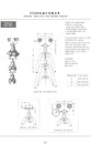
2-21.2504特殊圓形電纜滑車SPECIAL TROLLEY FOR ROUND CABLE 2504
2. C型軌及配件 C PROFILE CABLE TROLLEY 下載down load 2-1.C型軌及電纜滑車 FLEXIBLE ENERGY SUPPLY SYSTEMS THROUGH CABLE TROLLEYS 2-2.2331-1 C型軌及配件PROFILE 2331-1 AND ACCESSORIES 2-3.2331-2 C型軌及配件PROFILE 2331-2 AND ACCESSORIES 2-4.2331-5 C型軌及配件PROFILE 2331-5 AND ACCESSORIES 2-5.2332和2400電纜滑車CABLE TROLLEY 2332 & 2400 2-6.2401和2330電纜滑車CABLE TROLLEY 2401 & 2330 2-7.2331和2400主導滑車 TOWING TROLLEY 2331 & 2400 2-8.2400和2401主導滑車 TOWING TROLLEY 2400 & 2401 2-9.2331接線盒主導滑車 STATION TOWING TROLLEY 2331 2-10.2400尾端夾 END CLAMP 2400 2-11.2338圓形電線特殊滑車 SPECIAL TROLLEY FOR ROUND CABLE 2338 2-12.2324特殊電纜滑車 SPECIAL CABLE TROLLEYS 2324 2-13.安裝組合MOUNTING ARRANGEMENT 2-14.其他配件OTHER SPARTS 2-15.其他配件OTHER SPARTS 2-16.2500 C型軌及配件PROFILE 2500 AND ACCESSORIES 2-17.2500電纜滑車及配件CABLE TROLLEY 2500 AND ACCESSORIES 2-18.2500電纜滑車及配件CABLE TROLLEY 2500 AND ACCESSORIES 2-19.2500電纜滑車及配件CABLE TROLLEY 2500 AND ACCESSORIES 2-20.2500電纜滑車及配件CABLE TROLLEY 2500 AND ACCESSORIES 2-21.2504特殊圓形電纜滑車SPECIAL TROLLEY FOR ROUND CABLE 2504 2-22.2330特殊圓形電纜滑車SPECIAL CABLE TROLLEYS 23302504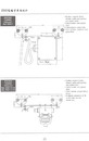
2-20.2500電纜滑車及配件CABLE TROLLEY 2500 AND ACCESSORIES-03
2. C型軌及配件 C PROFILE CABLE TROLLEY 下載down load 2-1.C型軌及電纜滑車 FLEXIBLE ENERGY SUPPLY SYSTEMS THROUGH CABLE TROLLEYS 2-2.2331-1 C型軌及配件PROFILE 2331-1 AND ACCESSORIES 2-3.2331-2 C型軌及配件PROFILE 2331-2 AND ACCESSORIES 2-4.2331-5 C型軌及配件PROFILE 2331-5 AND ACCESSORIES 2-5.2332和2400電纜滑車CABLE TROLLEY 2332 & 2400 2-6.2401和2330電纜滑車CABLE TROLLEY 2401 & 2330 2-7.2331和2400主導滑車 TOWING TROLLEY 2331 & 2400 2-8.2400和2401主導滑車 TOWING TROLLEY 2400 & 2401 2-9.2331接線盒主導滑車 STATION TOWING TROLLEY 2331 2-10.2400尾端夾 END CLAMP 2400 2-11.2338圓形電線特殊滑車 SPECIAL TROLLEY FOR ROUND CABLE 2338 2-12.2324特殊電纜滑車 SPECIAL CABLE TROLLEYS 2324 2-13.安裝組合MOUNTING ARRANGEMENT 2-14.其他配件OTHER SPARTS 2-15.其他配件OTHER SPARTS 2-16.2500 C型軌及配件PROFILE 2500 AND ACCESSORIES 2-17.2500電纜滑車及配件CABLE TROLLEY 2500 AND ACCESSORIES 2-18.2500電纜滑車及配件CABLE TROLLEY 2500 AND ACCESSORIES 2-19.2500電纜滑車及配件CABLE TROLLEY 2500 AND ACCESSORIES 2-20.2500電纜滑車及配件CABLE TROLLEY 2500 AND ACCESSORIES 2-21.2504特殊圓形電纜滑車SPECIAL TROLLEY FOR ROUND CABLE 2504 2-22.2330特殊圓形電纜滑車SPECIAL CABLE TROLLEYS 23302500-72500-7-c-162500-7-c-24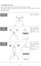
2-19.2500電纜滑車及配件CABLE TROLLEY 2500 AND ACCESSORIES-02
2. C型軌及配件 C PROFILE CABLE TROLLEY 下載down load 2-1.C型軌及電纜滑車 FLEXIBLE ENERGY SUPPLY SYSTEMS THROUGH CABLE TROLLEYS 2-2.2331-1 C型軌及配件PROFILE 2331-1 AND ACCESSORIES 2-3.2331-2 C型軌及配件PROFILE 2331-2 AND ACCESSORIES 2-4.2331-5 C型軌及配件PROFILE 2331-5 AND ACCESSORIES 2-5.2332和2400電纜滑車CABLE TROLLEY 2332 & 2400 2-6.2401和2330電纜滑車CABLE TROLLEY 2401 & 2330 2-7.2331和2400主導滑車 TOWING TROLLEY 2331 & 2400 2-8.2400和2401主導滑車 TOWING TROLLEY 2400 & 2401 2-9.2331接線盒主導滑車 STATION TOWING TROLLEY 2331 2-10.2400尾端夾 END CLAMP 2400 2-11.2338圓形電線特殊滑車 SPECIAL TROLLEY FOR ROUND CABLE 2338 2-12.2324特殊電纜滑車 SPECIAL CABLE TROLLEYS 2324 2-13.安裝組合MOUNTING ARRANGEMENT 2-14.其他配件OTHER SPARTS 2-15.其他配件OTHER SPARTS 2-16.2500 C型軌及配件PROFILE 2500 AND ACCESSORIES 2-17.2500電纜滑車及配件CABLE TROLLEY 2500 AND ACCESSORIES 2-18.2500電纜滑車及配件CABLE TROLLEY 2500 AND ACCESSORIES 2-19.2500電纜滑車及配件CABLE TROLLEY 2500 AND ACCESSORIES 2-20.2500電纜滑車及配件CABLE TROLLEY 2500 AND ACCESSORIES 2-21.2504特殊圓形電纜滑車SPECIAL TROLLEY FOR ROUND CABLE 2504 2-22.2330特殊圓形電纜滑車SPECIAL CABLE TROLLEYS 23302500-150-22500-150-52500-150-6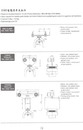
2-18.2500電纜滑車及配件CABLE TROLLEY 2500 AND ACCESSORIES-02
2. C型軌及配件 C PROFILE CABLE TROLLEY 下載down load 2-1.C型軌及電纜滑車 FLEXIBLE ENERGY SUPPLY SYSTEMS THROUGH CABLE TROLLEYS 2-2.2331-1 C型軌及配件PROFILE 2331-1 AND ACCESSORIES 2-3.2331-2 C型軌及配件PROFILE 2331-2 AND ACCESSORIES 2-4.2331-5 C型軌及配件PROFILE 2331-5 AND ACCESSORIES 2-5.2332和2400電纜滑車CABLE TROLLEY 2332 & 2400 2-6.2401和2330電纜滑車CABLE TROLLEY 2401 & 2330 2-7.2331和2400主導滑車 TOWING TROLLEY 2331 & 2400 2-8.2400和2401主導滑車 TOWING TROLLEY 2400 & 2401 2-9.2331接線盒主導滑車 STATION TOWING TROLLEY 2331 2-10.2400尾端夾 END CLAMP 2400 2-11.2338圓形電線特殊滑車 SPECIAL TROLLEY FOR ROUND CABLE 2338 2-12.2324特殊電纜滑車 SPECIAL CABLE TROLLEYS 2324 2-13.安裝組合MOUNTING ARRANGEMENT 2-14.其他配件OTHER SPARTS 2-15.其他配件OTHER SPARTS 2-16.2500 C型軌及配件PROFILE 2500 AND ACCESSORIES 2-17.2500電纜滑車及配件CABLE TROLLEY 2500 AND ACCESSORIES 2-18.2500電纜滑車及配件CABLE TROLLEY 2500 AND ACCESSORIES 2-19.2500電纜滑車及配件CABLE TROLLEY 2500 AND ACCESSORIES 2-20.2500電纜滑車及配件CABLE TROLLEY 2500 AND ACCESSORIES 2-21.2504特殊圓形電纜滑車SPECIAL TROLLEY FOR ROUND CABLE 2504 2-22.2330特殊圓形電纜滑車SPECIAL CABLE TROLLEYS 23302500-100-22500-100-52500-100-6