1-1-7.SAF-T-BAR C型電軌(C SERIES CONDUCTOR)
 點擊圖片放大
1-1-7.SAF-T-BAR C型電軌(C SERIES CONDUCTOR)
1.C&W電軌系統(SAF-T-BAR)新目錄
1-1.SAF-T-BAR C型電軌(C SERIES CONDUCTOR) 下載down load
1-2.SAF-T-BAR H型電軌(H SERIES CONDUCTOR) 下載down load
1-3.SAF-T-BAR T型電軌(T SERIES CONDUCTOR) 下載down load
1-4.INSUL-8 8字型電軌(INSUL-8 CONDUCTOR) 下載down load
1-5.INSUL-8側向8型電軌(INSUL-8 SIDE CONTACT CONDUCTOR BAR) 下載down load
1-6.CLUSTER電軌CLUSTER BAR 下載down load
Can be mounted so collector shoes enter from the bottom (vertical mode) or from the side (horizontal mode). Able to be factory curved to a minimum of 18 inches (457mm) radius with a maximum collector size of 35A.
Support Spacing: 5 ft (1.5 M)
Maximum rail temperature: 160OF (71OC) at 260 PSI (standard cover)
260OF (127OC) at 260PSI (medium temperature Lexan cover)
375OF (191OC) at 260 PSI (high heat fiberglass cover)
End Cap Part Number: CN100 ("Standard Heat" only)
1 Nominal current is based on 86OF (30°C) and is for 100% duty.
2 Complete with orange rigid "Standard Heat" PVC insulator cover, which has a 160° F (71O C) heat distortion point, 260psi. Self-extinguishing.
3 Complete with green rigid PVC insulator cover, which has a 160° F (71OC) heat distortion point, 260psi. Self-extinguishing. Some hand-safe options available, please consult Factory.
4 Complete with white rigid PVC insulator cover, which has a 160° F (71OC) heat distortion point, 260psi. Self-extinguishing. Some hand-safe options available, please consult Factory.
5 Complete with red Lexan "Medium Heat" insulator cover, which has a 260° F (127O C) heat distortion point, 260psi. Self-extinguishing.
6 Complete with fiber glass "High Heat" cover, which has 375° F ( 191O C) heat distortion point, 260psi. Self-extinguishing.
7 Series C and Series T are provided with the rail joint pre-mounted to the rail. If special cuts are required, the extra joint kit is available for series C.
8 Expansion Sections come with "Standard Heat" orange PVC covers. Medium Heat, High Heat, and green ground covers are also available. Please refer to the relevant section or contact factory.
更多商品
1-1-6.SAF-T-BAR C型電軌(C SERIES CONDUCTOR)
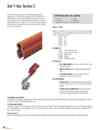
1.C&W電軌系統(SAF-T-BAR)新目錄 1-1.SAF-T-BAR C型電軌(C SERIES CONDUCTOR) 下載down load 1-2.SAF-T-BAR H型電軌(H SERIES CONDUCTOR) 下載down load 1-3.SAF-T-BAR T型電軌(T SERIES CONDUCTOR) 下載down load 1-4.INSUL-8 8字型電軌(INSUL-8 CONDUCTOR) 下載down load 1-5.INSUL-8側向8型電軌(INSUL-8 SIDE CONTACT CONDUCTOR BAR) 下載down load 1-6.CLUSTER電軌CLUSTER BAR 下載down load Series C Conductor Bars are roll-formed of galvanized steel or copper/steel laminate (250A) or copper (300A and 350A). The “U” shaped contact surface ensures positive tracking of the collector shoe and ensures good contact throughout the travel of the system. The standard material is supplied in 10 ft lengths with all necessary joining hardware. Installation is simple and requires only a jointing tool to connect the rails. Ampacity range: Based on continuous service with a 86OF (30OC) rise. Higher ratings can be obtained by increasing temperature rise and using high heat covers - Contact the Factory. CA90 90 CA110 110 CA250 250 CA300 300 CA350 350 Bar Material: CA90 1010 galvanized steel CA110 1010 galvanized steel CA250 Steel/copper CA300 Copper CA350 Electrolytic copper Bar Features: Skin-tight insulation runs cooler, will not deform under clamping pressure Metal Guideways assure positive tracking of collector shoe Flat contact surface for long conductor wear and greatest possible sliding contact area Collector Features: Contact shoe made with sintered copper and graphite, self-lubricating, draws current to collectors. Flat contact surface. Pantograph spring suspension of collector provides even pressure to shoe throughout stroke, yielding maximum electrical and mechanical performance.In wet and icy atmospheres, the system can be shielded with a protective hood for additional protection. In dirty and dusty atmospheres, mount the conductor in down-turned position (bottom entry).Atmospheric specifications Insulating cover options Standard is orange rigid PVC extrusion, 160OF (71OC) heat distortion point at 260 psi, self-extinguishing. Medium heat cover of red Lexan extrusion can be specified when necessary, 260OF (127OC) heat distortion point at 260 psi, self extinguishing. High heat fiberglass cover is available, 375OF (191OC) heat distortion. Long run options Push-in-place locking tabs are available if required for use on long runs with expansion gaps on copper and steel/copper conductor sections.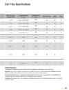
1-1-5.SAF-T-BAR C型電軌(C SERIES CONDUCTOR)
1.C&W電軌系統(SAF-T-BAR)新目錄 1-1.SAF-T-BAR C型電軌(C SERIES CONDUCTOR) 下載down load 1-2.SAF-T-BAR H型電軌(H SERIES CONDUCTOR) 下載down load 1-3.SAF-T-BAR T型電軌(T SERIES CONDUCTOR) 下載down load 1-4.INSUL-8 8字型電軌(INSUL-8 CONDUCTOR) 下載down load 1-5.INSUL-8側向8型電軌(INSUL-8 SIDE CONTACT CONDUCTOR BAR) 下載down load 1-6.CLUSTER電軌CLUSTER BAR 下載down load Safety Precautions Please observe the following safety recommendations when selecting, installing or maintaining any conductor bar system. Regulations: Please ensure the system is selected, located and installed in accordance to all relevant local, state and federal standards and regulations and that unauthorized personnel do not have access to any part of the system when energized. Electrical Connections: Please ensure all electrical connections, including connection to the conductor bar power feed and installation and connection of the current collectors is conducted by an experienced and qualified personnel. Lock-Out: During installation and/or service, please always lock out/tag out all electrical power before commencing any works on or around the conductor bar system.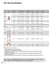
1-1-4.SAF-T-BAR C型電軌(C SERIES CONDUCTOR)
1.C&W電軌系統(SAF-T-BAR)新目錄 1-1.SAF-T-BAR C型電軌(C SERIES CONDUCTOR) 下載down load 1-2.SAF-T-BAR H型電軌(H SERIES CONDUCTOR) 下載down load 1-3.SAF-T-BAR T型電軌(T SERIES CONDUCTOR) 下載down load 1-4.INSUL-8 8字型電軌(INSUL-8 CONDUCTOR) 下載down load 1-5.INSUL-8側向8型電軌(INSUL-8 SIDE CONTACT CONDUCTOR BAR) 下載down load 1-6.CLUSTER電軌CLUSTER BAR 下載down load Maximum voltage for all Series - 600 volts. 1 Nominal current is based on 30°C and 100% duty cycles. 2 Weight includes both the bar material and the insulating cover. 3 AC impedance is measured in ohms/ft based on 30°C and the largest typical bar centers. Please adjust as necessary for other ambient temperatures and/or bar centers. 4 DC resistance is measured in ohms/ft based on 30°C and the largest typical bar centers. Please adjust as necessary for other ambient temperatures and/or bar centers. 5 Maximum nominal voltage is based on standard insulation materials and spacing. For higher voltage applications, please consult the factory.
1-1-3.SAF-T-BAR C型電軌(C SERIES CONDUCTOR)
1.C&W電軌系統(SAF-T-BAR)新目錄 1-1.SAF-T-BAR C型電軌(C SERIES CONDUCTOR) 下載down load 1-2.SAF-T-BAR H型電軌(H SERIES CONDUCTOR) 下載down load 1-3.SAF-T-BAR T型電軌(T SERIES CONDUCTOR) 下載down load 1-4.INSUL-8 8字型電軌(INSUL-8 CONDUCTOR) 下載down load 1-5.INSUL-8側向8型電軌(INSUL-8 SIDE CONTACT CONDUCTOR BAR) 下載down load 1-6.CLUSTER電軌CLUSTER BAR 下載down load System Components: Conductor Bar: Selected to meet ampacity, voltage drop, duty cycle, environmental, and application requirements. Rail Joints : Required for each connection, unless the joint is pre-mounted to the bar - Series C and Series T only. Hanger/Anchor Clamps: Must be installed at the spacing specified in this catalog. Anchor points must be determined and set according to the expansion of the system. Hangers must be installed at least 6"(152 mm) from any rail joint or power feed to allow for adequate system expansion. Support Arms: Support arms are required at each hanger clamp location and must be of sufficient strength to ensure safe suspension of the conductor bar system. Power Feeds: The ideal location for a single power feed is the center point of the system to yield the minimum voltage drop. A minimum of one power feed is required per pole. Expansion Sections: Expansion sections are required for installations beyond certain total system lengths - See Pg. 65. End Caps: End caps are required to insulate the system at the rail ends. Collectors: Collectors must be selected to meet the amperage requirements of crane/machine and the related duty cycle of the application. Collector Towing Arm: Is required for each set of current collectors and is required to tow the collector assembly. National Electric Code Ampacity Requirements For one motor, use 100% of motor nameplate full load ampere rating. For multiple motors on a single crane or hoist, the minimum circuit ampacity of the power supply conductors on a crane or hoist shall be the nameplate full load ampere rating of the largest motor or group of motors for any single crane motion, plus 50% of the nameplate full load ampere rating of the next largest motor or group of motors. For multiple cranes and/or hoists supplied by a common conductor system, compute the motor minimum ampacity for each crane as in step (2), add them together and multiply the sum of the demand factor from the following table: Number of cranes Demand factor 2 .95 3 .91 4 .87 5 .84 6 .81 7 .78 For constant loads such as magnets, lights, and air conditioners, etc., plus high duty cycles, use full load amperage, in selecting conductor size. System Calculations The Specification Data Sheets on pages 6-7 will help you collect information about your application. Also, see Pgs. 83-88 for other considerations that will help you choose the correct conductor bar system for your application. Please also refer to your relevant local, state/provincial, and federal regulations to make sure that the correct material is selected. In the USA, refer to calculation methods used in NEC 610-14(e). For constant loads such as magnets, lights, and air conditioners, etc., plus high duty cycles, use full load amperages to select conductor size.Once these values are determined, depending upon the ambient temperature, apply ampacity correction factors (as per table 610.14(A). Voltage Drop Calculation - See also Pgs. 84 and 87. As most motors are designed to operate with a 2.5% to 5% voltage drop, divide volts lost by line voltage to determine if a larger conductor or additional feed points are required. See tables for values Z and R. 3 phase AC Volts lost = 1.73 x Z x Length in feet from feed x Ampere load 1 phase AC Volts lost = 2 x Z x Length in feet from feed x Ampere load DV Volts lost = 2 x R x Length in feet from feed x Ampere load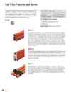
1-1-2.SAF-T-BAR C型電軌(C SERIES CONDUCTOR)
1.C&W電軌系統(SAF-T-BAR)新目錄 1-1.SAF-T-BAR C型電軌(C SERIES CONDUCTOR) 下載down load 1-2.SAF-T-BAR H型電軌(H SERIES CONDUCTOR) 下載down load 1-3.SAF-T-BAR T型電軌(T SERIES CONDUCTOR) 下載down load 1-4.INSUL-8 8字型電軌(INSUL-8 CONDUCTOR) 下載down load 1-5.INSUL-8側向8型電軌(INSUL-8 SIDE CONTACT CONDUCTOR BAR) 下載down load 1-6.CLUSTER電軌CLUSTER BAR 下載down loadThe Saf-T-Bar line of conductor bar products was originally manufactured by the Howell Corporation and is now part of the Conductix-Wampfler product family. Saf-T-Bar is designed to provide customers with a cost effective, yet highly reliable system for the transmission of electrical energy. Each system is designed with simplicity and reliability in mind. The performance of the product line has been proven in the field for over 30 years. Series C The Series C range of conductor bars is available in capacities from 90 amps through toing pressure. The push-pin joint system requires no loose hardware to install. C Series bars are available with standard rigid PVC insulation, or optional medium-heat Lexan or high-heat fiberglass insulation. Available accessories include single or tandem collectors, various single or multi-pole hanger clamps (3 or 4 pole), isolation sections, and expansion sections for longer runs.350 amps and can be mounted in any plane. The "C"-shaped metal guideway provides positive tracking of the collector shoe within the profile of the bar; the shoe will track with or without the cover. The flat contact surface of the bar and copper graphite shoe yields minimal shoe wear. Skin-tight insulation runs cooler and will not deform under clamp- Series H The Series H Conductor Bar has the highest current rating of the Saf-T-Bar lines, available in four amperages; 500, 750, 1000, and 1500 amps. Each of the profiles are constructed of extruded aluminum with an integrated stainless steel contact channel rolled into aluminum material to ensure positive tracking of the collector and optimum collector shoe wear. This series is available with standard or high temperature insulation covers and a vast array of accessories. Series T The T Series system is unique to Conductix-Wampfler and features a captive collector concept resulting in an extremely compact system. The conductor bars are supplied with pre-mounted joints. Using the jointing tool, adjoining rails can be connected quickly and easily. Special spring collectors are constructed of a chromium-copper material which ensures optimized collector wear. Available in 65 amp galvanized steel with a full line of accessories.
1-1-1.SAF-T-BAR C型電軌(C SERIES CONDUCTOR)
1.C&W電軌系統(SAF-T-BAR)新目錄 1-1.SAF-T-BAR C型電軌(C SERIES CONDUCTOR) 下載down load 1-2.SAF-T-BAR H型電軌(H SERIES CONDUCTOR) 下載down load 1-3.SAF-T-BAR T型電軌(T SERIES CONDUCTOR) 下載down load 1-4.INSUL-8 8字型電軌(INSUL-8 CONDUCTOR) 下載down load 1-5.INSUL-8側向8型電軌(INSUL-8 SIDE CONTACT CONDUCTOR BAR) 下載down load 1-6.CLUSTER電軌CLUSTER BAR 下載down load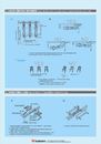
6-19.如何按裝I型電軌固定方棒和絕緣電軌 How to install I-Type Fix Square Bar and I-Type Insulated Conductor Rails
6.絕緣安全電軌 Insulated Conductor Rails/Bars 下載down load 6-1.絕緣安全電軌 Insulated Conductor Rails/Bars 6-2.索引 Index 6-3.銅導軌的安全電流一覧表 Safety Current Table of Copper Busbar 6-4.3相.4相.6相絕緣安全電軌 3P.4P.6P Insulated Conductor Rails Insulated Conductor Rails 6-5.尾端張力和入電 End Tension & Power In 6-6.集電架 Current Collector 6-7.中間入電 Middle Power Feeding 6-8.支架 Supports 6-9.3相.4相.6相絕緣安全電軌按裝示意圖 3P . 4P . 6P Insulated Conductor Rails Outline Design 6-10.支架設計 Supports Design 6-11.支架設計 Supports Design 6-12.I 型絕緣安全電軌 I-Type Insulated Conductor Rails 6-13.I 型尾端拉力和入電 I-Type End Tension & Power In 6-14.I 型碳刷 I-Type Collector Shoe 6-15.I 型絕緣安全電軌安裝示意圖 I-Type Insulated Conductor Rails Outline Design 6-16.I 型絕緣電軌超過30M長時安裝示意圖 Installation Design for I-Type Insulated Conductor Rails above 30 meters 6-17.環繞安裝 Around type 6-18.如何安裝I型電軌之尾端張力和入電 How to install I-Type End Tension & Power In 6-19.如何按裝I型電軌固定方棒和絕緣電軌 How to install I-Type Fix Square Bar and I-Type Insulated Conductor Rails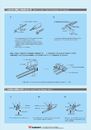
6-18.如何安裝I型電軌之尾端張力和入電 How to install I-Type End Tension & Power In
6.絕緣安全電軌 Insulated Conductor Rails/Bars 下載down load 6-1.絕緣安全電軌 Insulated Conductor Rails/Bars 6-2.索引 Index 6-3.銅導軌的安全電流一覧表 Safety Current Table of Copper Busbar 6-4.3相.4相.6相絕緣安全電軌 3P.4P.6P Insulated Conductor Rails Insulated Conductor Rails 6-5.尾端張力和入電 End Tension & Power In 6-6.集電架 Current Collector 6-7.中間入電 Middle Power Feeding 6-8.支架 Supports 6-9.3相.4相.6相絕緣安全電軌按裝示意圖 3P . 4P . 6P Insulated Conductor Rails Outline Design 6-10.支架設計 Supports Design 6-11.支架設計 Supports Design 6-12.I 型絕緣安全電軌 I-Type Insulated Conductor Rails 6-13.I 型尾端拉力和入電 I-Type End Tension & Power In 6-14.I 型碳刷 I-Type Collector Shoe 6-15.I 型絕緣安全電軌安裝示意圖 I-Type Insulated Conductor Rails Outline Design 6-16.I 型絕緣電軌超過30M長時安裝示意圖 Installation Design for I-Type Insulated Conductor Rails above 30 meters 6-17.環繞安裝 Around type 6-18.如何安裝I型電軌之尾端張力和入電 How to install I-Type End Tension & Power In 6-19.如何按裝I型電軌固定方棒和絕緣電軌 How to install I-Type Fix Square Bar and I-Type Insulated Conductor Rails 1. Cut off insulated plastic PVC material at 90mm from the end of I-Type Insulated Conductor Rails 2. Put Washer and Terminal Plate into Copper Conductor material of I-Type Insulated Conductor Rails, then bend backward Copper Conductor material and touch with Ter minal Plate 3. Place Cover on and complete 1. Connect Power Cable Wire with Terminal Plate and then place Cover on I-Type Insulated Conductor Rails